Solera
®
Awning
Smart Arm
Installation and Owner’s Manual
(For Aftermarket Applications)
www.lci1.com 574-537-8900
Page 7
Solera® Awning Smart Arm Aftermarket Manual
9. Run the wires from the unit through the provided access
hole in the mount arm (Fig.8)�
NOTE: If top install, make sure all wires are always on the
outside of the pin that secures the pitch arm to the mount arm�
(Fig.7)�
10. Connect the 10 AWG power wire from the unit to the power
wire on the Smart Arm Touch Pad�
11. Connect the extend “EXT IN” and retract “RET IN” wires to
the switch inside the coach�
12. Tuck loose wiring into the hole in wall of the unit and seal
with silicone sealant or butyl tape�
13. Reinstall the Smart Arm Touch Pad and snap clip (Fig.9)�
14. Reinstall the wire covers�
NOTE: Power to the Smart Arm Touch Pad will time out after
ve minutes of being idle.
Installing The LED Light
- Optional
1. The light wire is under the 4-inch wire cover at the top of the
arm (Fig.10)� Remove the wire cover�
2. Connect the red wire from the light to the red 20 AWG light
wire in the arm�
3. Connect the black wire from the light to the black 20 AWG
wire in the arm�
4. The light wire must be routed over the top of the mounting
arm (Fig.10)�
5. Connect green wire marked “LGT IN” to the light power
wire from the unit�
NOTE: The ground wire from the light switch inside the unit
will be capped off�
Installing The Wind Sensor
- Optional
1. Locate the Wind Sensor (Fig.11)�
2. Locate Mounting Block (Fig.12) below the drive head on the
outer arm�
3. Attach the Wind Sensor wires (Fig.12) to the wires from the
Smart Arm Touch Pad by snapping connectors together (Fig.12)�
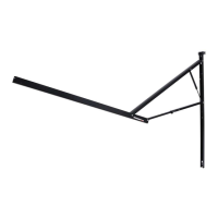
LED light
top of
mounting arm
Fig.10
drive head
top of
outer arm
wire connector
to power
drive arm
wind sensor
wire
connector
wind sensor
A
wind sensor
mounting block
wind sensor
mounting hole
screw
Fig.11
Fig.12
wind sensor mounting hole