Rev: 05.20.2022 Page 16 CCD-0001745
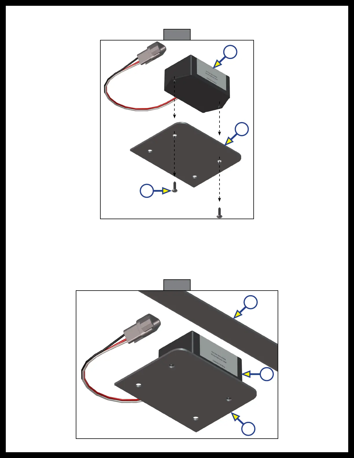
Fig. 21
C
B
A
Fig. 22
C
A
B
5. Remove the screws (Fig. 21A) from the rear sensor (Fig. 21B) and mounting plate (Fig. 21C) and remove
the old sensor from the mounting plate.
6. When installing a new rear sensor, dry-fit the mounting plate (Fig. 22A) and the new rear sensor
(Fig.21B) to the cross-member (Fig. 21A).
NOTE: The pre-drilled holes in the plate are for mounting the rear sensor to the plate.
7. Mark on the plate where the rear sensor will set.
NOTE: Space between the sensor and the crossmember must be left so the wire harness will not
bepinched.
 Loading...