Rev: 05.20.2022 Page 17 CCD-0001745
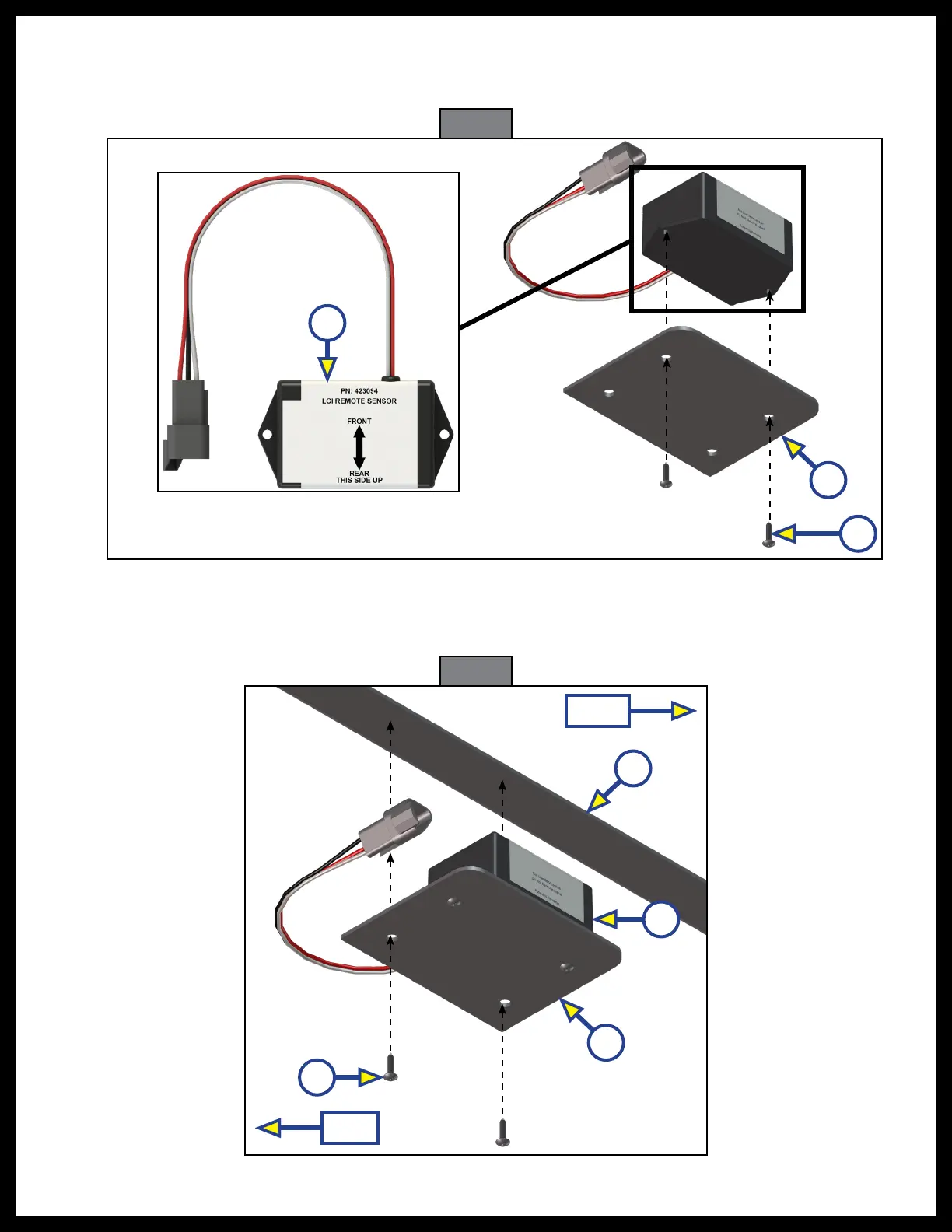
Fig. 23
Fig. 24
C
B
A
8. Attach the replacement rear sensor (Fig. 23A) to the mounting plate (Fig. 23B) using two
⁄"
hex head
self-tapping screws (Fig. 23C). Proper orientation of the rear sensor is imperative for the correct operation
of the leveling system.
9. Attach the mounting plate (Fig. 24A) and replacement sensor (Fig. 24B) assembly to the crossmember
(Fig. 24C) using two
⁄"
hex head self tapping screws (Fig. 24D). Make sure the mounting plate is
centered side-to-side on the frame and that the sensor is oriented properly (Fig. 24).
B
C
A
D
Front
Rear
 Loading...