Figure 8
2. Attach the head to the pump casing. Insert four head
bolts 90° apart and tighten to 25 ft•lbs (34 Nm).
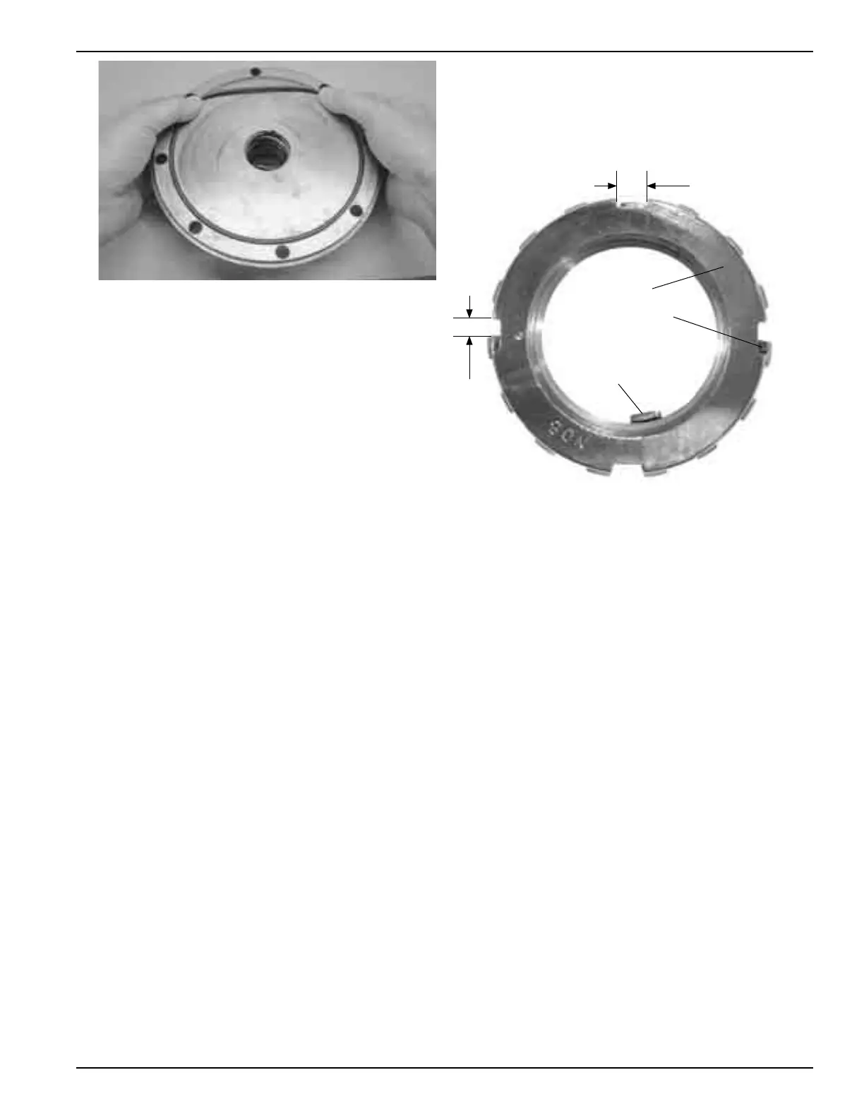
3. Mechanical Seal
Apply a small amount of light oil in the head recess. Press
the mechanical seal assembly into the recess of the head
so the seal jacket drive tabs face the rotor. The pin in the
stationary seat must be between the lugs in the back of
the head recess (see Figure 7).
4. Hand pack the ball bearing with grease. See the “Bearing
Lubrication” section for recommended grease.
5. Insert the bearing into the head recess. The bearing
balls should face outward, and the grease shield
should face inward. Make sure the bearing is square
and completely seated against the mechanical seal.
6. Turn the pump casing around to reassemble the
opposite side.
7. Place vanes into the upper rotor-shaft slots. Ensure
the curved tip of each vane faces radially outward and
all in the same direction of rotation (see Figure 10).
8. While cupping these vanes in place, rotate the rotor-shaft
over 180° and install the vane drivers.
9. Place rotor-shaft and vane assembly into pump case
with the vanes on the bottom. Ensure the ribs in the
vanes face the direction of pump rotation (see Appendix
E for parts details and pump rotation arrows).
10. Place the remaining vanes into the upper rotor-shaft slots
facing the same direction as the first vanes.
11. Install the remaining head, mechanical seal, and bearing
as mentioned in steps 1 through 5. Apply a thin coating
of motor oil to the shaft to facilitate installation.
12. Rotate the shaft by hand to engage the seal jacket
driver tabs. Check for binding or tight spots. If the rotor
does not turn freely, use a soft faced mallet and lightly
tap the rims of the heads until the rotor is in the correct
position. Tighten all remaining head bolts for each head
to 25 ft•lbs (34 Nm) of torque.
13. Locknut Installation
All bearing locknuts and lockwashers MUST be positioned
and adjusted properly. Overtightening locknuts can lead
to bearing failure or broken lockwasher tabs. If locknuts
are loose, the rotor will shift against the heads and
cause considerable wear (see Figure 9).
1 stop
equals
.001 in.
rotor
movement
2 stops equals one
tab (.002 in.)
B
A
(Inner tab fits
in rotor slot)
Locknut
Lockwasher
Figure 9: Locknut and lockwasher adjustment
13 .1 On both ends of the pump shaft, slide on a lockwasher,
with the tabs facing outward, and then tighten a
locknut with the tapered end inward. Make sure the
inner tab (A) of the lockwasher is inserted in the slot
of the shaft threads. Bend slightly, if necessary.
13.2 Carefully tighten both locknuts until the bearings
have reached the bottom of the head recess. DO
NOT overtighten, Make sure the inner tab of the
lockwasher does not shear.
13.3 Loosen both locknuts one complete turn.
13.4 Tighten one locknut until you can feel a slight rotor
drag while turning the shaft by hand.
13.5 Back the locknut off one width of the lockwasher tab
(B). To secure the locknut, bend the closest aligned
lockwasher tab into the slot of the locknut. The pump
should now turn freely when rotated by hand.
13.6 Hand-tighten the opposite locknut until it is snug
against the bearing. Then, with a spanner wrench,
tighten the locknut one width of the lockwasher tab.
Tighten just past the tab width and then back off the
locknut until the tab is aligned with the slot of the
locknut. To secure the locknut, bend the aligned
lockwasher tab into the slot of the locknut. The pump
should still turn freely when rotated by hand.
13.7 Check the adjustment. The locknut and lockwasher
should turn back and forth by hand. If this is not
possible, one or both locknuts are too tight. They
must be alternately loosened one stop at a time
(.001 in.) (25 microns). Begin with the locknut
adjusted last.
11
 Loading...