vertical line from the tank must not exceed 12 feet (3.7
m) in length.
• The inlet must be the same size or next size larger than
the suction on the pump.
• Use an eccentric swage at the pump inlet nozzle to
change the line size (flat side up).
• Make certain the inlet line is level or sloped downward
to the pump.
• A strainer of the “Y” type, with 20 mesh screen or 1/16
in. perforated steel, must be on the inlet line of the
pump. (Mesh size indicates the number of openings
per lineal inch).
• Use a flexible connection in the pump inlet and outlet
piping to compensate for piping strains.
• The Inlet piping must be free of air leaks.
• All piping must be supported to avoid stress to the
pump casing.
• Potential risk due to local conditions regarding the
installation and operation (e.g. poor ventilation and
additional risks due to other elements in the vicinity, etc.).
• Qualification of the personnel.
• Type of liquid being transferred.
• Specific safety measures to be applied (e.g. gas
detection, automatic shut-off valves, personal protective
equipment, etc.).
Driver Installation
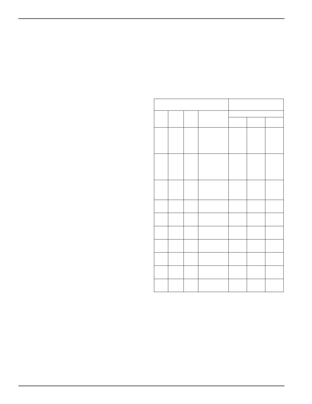
The wiring of your electric motor is extremely important and
must be done by a competent electrical contractor. The
following wire sizing chart indicates the minimum standards
for wire sizes.
Improper motor wiring will cause expensive motor difficulties
from low voltage. If you suspect you have low voltage, call
your power company. Connecting your motor for the voltage
you have available is important too. The motors furnished
with the stationary pumps are usually dual voltage, so
you must be sure of the voltage your power company is
supplying you. Your motor will be completely ruined if it is
connected to the wrong voltage.
A humid climate can cause problems, particularly in
explosion proof motor applications. The normal breathing
of the motor, and alternating between being warm when
running and cool when stopped, often will cause moist
air to be drawn into the motor housing. This moist air will
condense, and may eventually add enough free water to
the inside of the motor to cause it to fail. To prevent this,
make a practice of running the motor and pump at least
once a week on a bright, dry day for an hour or so (pumping
through the bypass system). In this period the motor will
heat up and vaporize the condensed moisture, and drive it
out of the motor. No motor manufacturer will guarantee an
explosion-proof or totally enclosed motor against damage
from moisture.
Engine drivers pose a special consideration. The
manufacturer’s instructions must be followed. When the
stationary pump is equipped with an engine from the
factory, the engine speed should normally not exceed 1,800
RPM. Excessive engine speed will overload the engine and
cause early failure. The engine loses 3% of its power for
every 1,000 ft (305 m) above sea level, so if your installation
is at a higher altitude than normal, consult the factory.
Motor
Recommended wire size,
AWG
1
Hp
Motor
phase
Volts
Approximate
full load
amperes
Length of run (ft)
0–100 to 200 to 300
31115 34.0 6 4 2
220 17.0 12 8 8
3230 9.6 121212
460 4.8 12 12 12
5 1 115 56.0 4 1 1/0
230 28.0 10 6 4
3 230 15.2 12 12 10
460 7.6 12 12 12
7-1/2 1 230 40.0 8 6 4
3 230 22.0 10 10 8
450 11.0 121212
10 3 230 28.0 8 8 8
460 14.0 121212
15 3 230 42.0 6 6 6
460 21.0 101010
20 3 230 54.0 4 4 4
460 27.0 8 8 8
25 3 230 68.0 2 2 2
460 34.0 6 6 6
30 3 230 80.0 1 1 1
460 40.0 6 6 6
40 3 230 100.0 2/0 2/0 2/0
460 52.0 4 4 4
50 3 230 130.0 3/0 3/0 3/0
460 65.0 2 2 2
1
Based upon 3% voltage loss copper wire type TW. Single phase
motor calculations are based on two times distance.
Operation of the PT-Series
Stationary Pump
Performance curves are provided in Appendix C.
The following steps should be performed for the initial
pumping operation:
1. Make sure the strainer screen is clean.
2. Rotate the pump by hand.
8