14. If you have the standard bypass valve, remove the
bypass valve cap and turn the adjustment screw
counterclockwise to relieve the spring tension.
Remove the four 3/8 in. bolts from the bypass valve
cover. Use caution as a small amount of spring
tension will remain on the bypass valve spring
before complete bolt removal. Inspect bypass
valve, spring, and bypass valve cap gasket for wear,
abrasions, etc. Replace if damage is found.
15. If you have an Air Operated Valve (AOV), ensure the air
supply pressure has been relieved and the supply line
disconnected from the valve housing. Remove the AOV
cap and discard the O-ring from underneath. Remove
the retainer ring and locknuts from the adjustment stem.
Remove the four 3/8 in. bolts and lockwashers from
the AOV housing. Carefully remove the AOV assembly
from the pump. Remove and discard the gasket and
clean the gasket areas. Remove the two recessed-
head machine screws and the diaphragm cover plate.
Slide the diaphragm assembly out from the housing.
Remove the intermediate vent plate from between the
two diaphragms. Inspect the diaphragms, spring, and
valve for abrasions and replace if necessary.
Vane Replacement
NOTICE: ONLY QUALIFIED TECHNICIANS SHOULD
PERFORM MAINTENANCE AND THEY MUST FOLLOW
THE APPROPRIATE PROCEDURES AND WARNINGS
PRESENTED IN MANUAL.
1. Follow steps 2–6 in the “Pump Disassembly Instructions”
section of this manual to remove the head assembly
from the non-PTO side of the pump.
2. Turn the shaft with your hand until a vane is in the top
(12 o’clock) position of the rotor. Remove the vane.
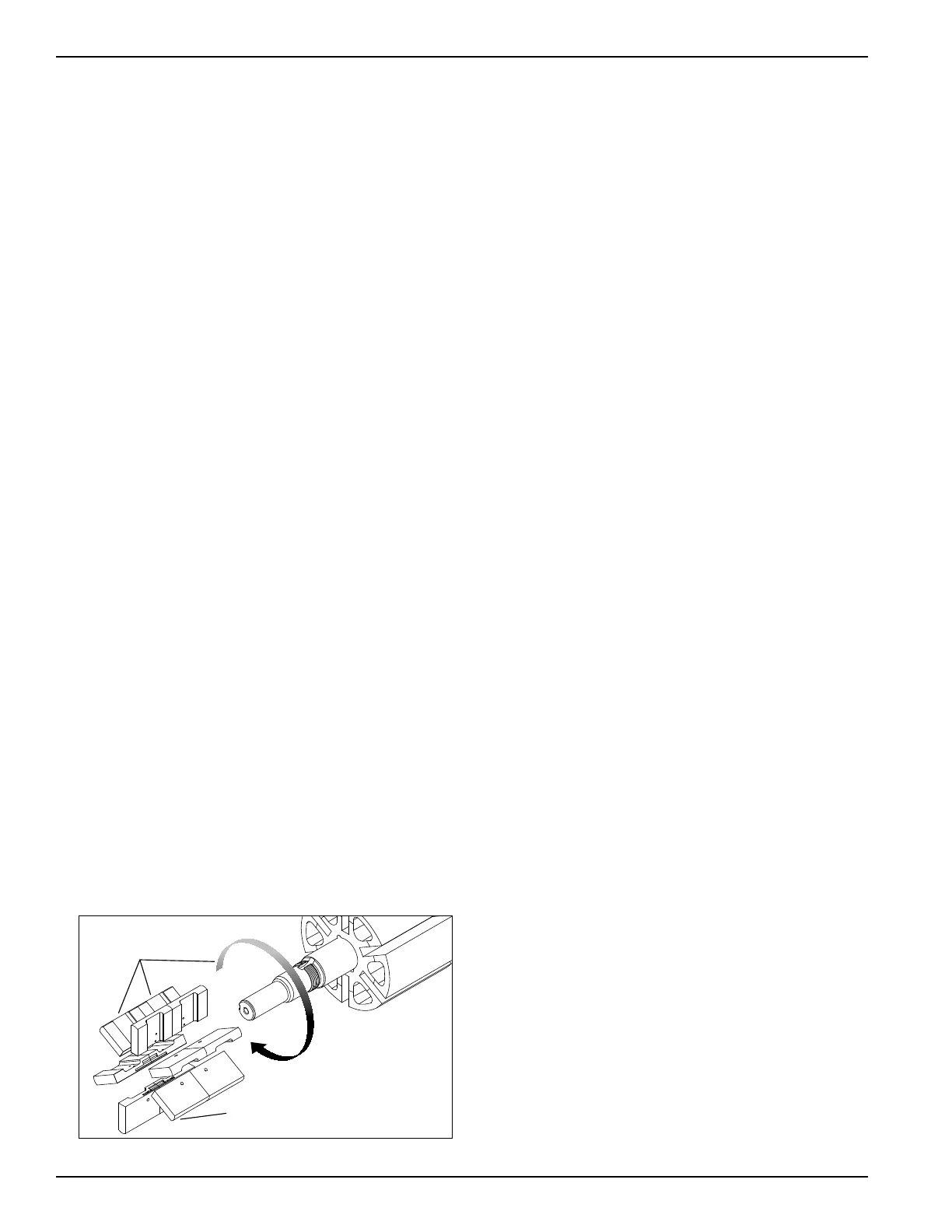
3. Position a new vane so the rounded edge faces out
from the pump and the relief grooves face towards the
direction of rotation (see Figure 10).
4. Repeat steps 2 and 3 until all vanes have been replaced.
5. Follow steps 2–7 and 12–13 of the “Pump Assembly
Instructions” section of this manual to reassemble
the pump.
Relief grooves
face the direction
of rotation
Rounded edge out
Figure 10: PT30 model shown above
Bypass Valve Assembly
1. Place the bypass valve into the bypass valve bore of
the pump casing with the fluted end inward.
2. Insert the bypass valve spring and spring guide
against the bypass valve.
3. Attach a new bypass valve gasket and the bypass
valve cover onto the pump casing.
4. Tighten the bypass valve adjusting screw into the
bypass valve cover until it makes contact with the
spring guide.
NOTICE: THE BYPASS VALVE SETTING MUST BE
TESTED AND PROPERLY ADJUSTED BEFORE
PUTTING THE PUMP INTO SERVICE. PLEASE SEE
“BYPASS VALVE ADJUSTMENT”.
5. After the bypass valve has been adjusted correctly,
attach the bypass valve cap and gasket.
Air Operated Valve (AOV) Assembly
1. Install the intermediate vent plate between the two
diaphragms ensuring proper orientation with the screw
holes in the housing. Slide the diaphragm assembly
into the housing and install the diaphragm cover plate
and recessed-head machine screws and tighten
securely. Install this assembly with the valve, spring,
and gasket to the pump using the four 3/8 in. bolts
and lock washers and torque to 15 ft•lbs. Install both
locknuts all the way down the adjustment stem and
replace the retainer ring. Install the new O-ring and
AOV cap. Refer to Air Operated Valve Adjustment for
adjustment procedure.
2. Grease bearings per the instructions listed under
Maintenance of Your Pump System.
3. Install the pump according to the installation guidelines
mentioned previously.
12