Installation of the PT-Series
Truck Pump
The mechanical installation of the PT-Series pump is a simple
matter. A rotation arrow is located on the side of the pump.
Examine the PTO and determine the direction of its rotation
before installing the pump. The PT-Series pump will match
either PTO rotation. Connect the drive shaft to the pump shaft
that turns the pump in the direction of the arrow.
The PTO SELECTION is important. For maximum
performance , the pump requires a PTO with an average
output speed of 500 to 700 RPM. In addition, the truck engine
must be operating at the appropriate RPM to maintain oil
pressure, water circulation, and the electrical system.
THE DRIVESHAFT that connects the pump to the PTO
should be of the “splined” or slip type. This type of driveshaft
permits the shaft to adjust for PTO movement and twisting
of the truck frame. A fixed driveshaft will transfer the
forces directly to the pump and PTO and shorten the life
of both considerably. The yokes of the driveshaft universal
joints must be positioned as shown in Figure 1. Improper
positioning will cause premature wear and potentially
destroy the bearings in the pump and PTO.
INLET PIPING should be as short as possible and at
least the minimum diameter specified for the model with
few restrictions so that the pressure drop is limited.
The outlet piping should include the following:
1. A pressure gauge should be installed in the pump
outlet or near it. A pressure gauge is necessary to
determine the efficiency of your pumping system.
2. If a meter with an air eliminator is installed, never pipe
the eliminator directly into the pump inlet piping or
into the liquid part of the system at any point (refer to
the meter installation manual).
3. The discharge piping should be at least the same size
as the meter piping.
Power Take-Off Drive Systems
Proper pump operation and long life is directly dependent
upon a good drive system. Many truck pumps utilize a power
train consisting of shafts and universal joints located between
the power take-off shaft of the truck engine and the pump.
There are several basic principles that should be followed
in designing a PTO drive. To produce a workable power
train that results in long pump life and reduced drive wear,
these principles SHOULD NOT be violated.
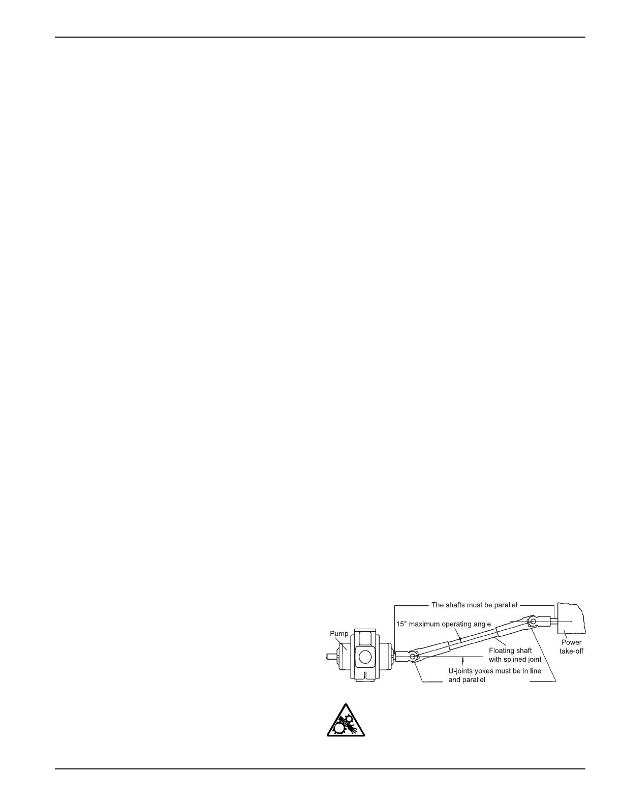
First, the driver shaft and the driven shaft must be parallel
to one another within plus or minus one degree. Improper
alignment will cause jerking and back and forth “whip” to the
pump shaft; thereby imparting a surging pulsation to the liquid
flow which results in noise, vibration and abnormal wear.
Second, the angle of the ‘’floating’’ shaft should be within
the limits for the particular equipment being used (usually
a maximum of 15° at pump speeds up to 800 RPM). To
ensure that shaft expansion or contraction does not distort
the drive system, a splined slip joint should be placed
between the two universal joints. Again, the drive shaft
should be of the “splined” or slip type to permit the shaft to
adjust for PTO movement and twisting of the truck frame. A
fixed drive shaft transmits the forces directly to the pump
and PTO which will shorten the life of both considerably.
Third, the yokes of the drive shaft universal joints must be
in a parallel position. Figure 1 below illustrates the proper
arrangement of the yokes.
Improperly installed U-joints will cause premature failure of
U-joints as well as bearings in the pump and PTO. Properly
mounted, the second universal gives uniform motion to
the drive shaft by compensating for the rotational error
introduced by the first U-joint. An even number of universal
joints (2, 4, 6 etc.) should always be used. An odd number
of U-joints will cause unbalanced pump shaft rotation. This
problem becomes greater with increased angularity.
Other points to consider include the proper sizing of the
shaft components with a maximum horsepower load to be
expected, good alignment of hanger bearings and proper
pump coupling alignment.
Improper PTO systems account for a high percentage of
truck pump failures. Always remember to disengage the
clutch before shifting the PTO into gear. Shifting the PTO into
gear without disengaging the clutch imparts an enormous
shock on the PTO, drive shaft, pump and meter and will
soon damage one or all of them.
For proper installation of pump drives, follow the rules
listed below:
1. Driver shaft and pump shaft must be parallel, plus or
minus one degree.
2. Operating angle of the ‘’floating’’ shaft must be 15°
maximum.
3. Universal yokes must be in line and parallel.
4. Splined slip joints must be used where needed.
5. Use an even number of universal joints.
Figure 1: Shaft alignment
Note: A drive shaft guard between the pump and
PTO should be installed (not shown).
6. Always use the least practical number of shafts.
5