PTO selection and drive system design is extremely important.
The PTO should have an average output speed up to 640 RPM
to maximize the performance of the PT-Series pump when the
truck engine is operating at the recommended speed.
The designer of the drive system must select a PTO drive
shaft capable of meeting the torque requirements of the
pumping system.
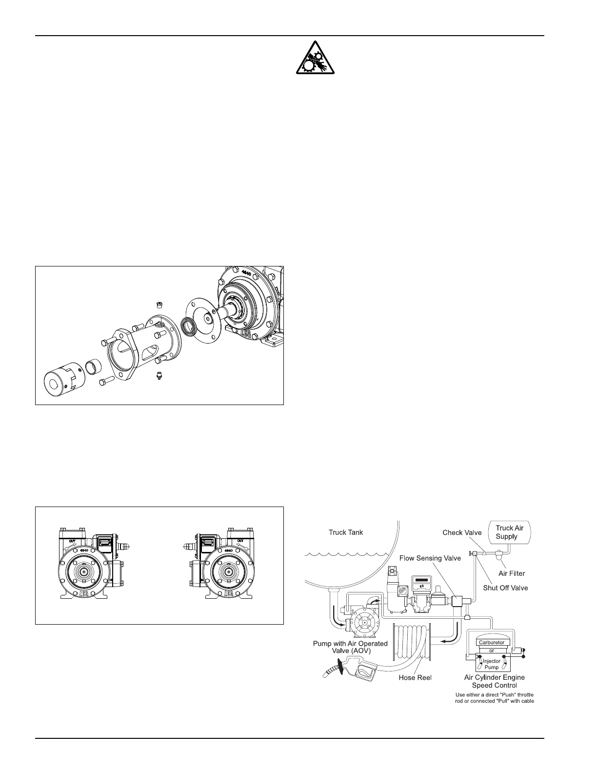
Hydraulic Drive Installation
Hydraulic motors must be well supported and keep their
shafts parallel to the pump shaft. To drive PT pumps
hydraulically, Liquid Controls Group provides a close-
coupled hydraulic motor adapter. The adapter aligns the
hydraulic motor drive and the pump shaft via a lockring
and a flexible coupling connected to a keyed shaft. This
adapter must be lubricated with grease at least every three
months. Refer to the “Bearing Lubrication” section of this
manual for instructions.
Figure 2: Hydraulic Drive (see Appendix E for Part Details)
Pump Rotation
For proper pump rotation, make sure the pump’s rotation
arrows match the pump driver rotation (see Appendix E for
parts details). NOTE: PT-Series pumps are double ended
shafts and can be mounted in either position.
Direction of Rotation
Left hand/counter clockwise rotation
(PT25)
Right hand/clockwise rotation
(PT25)
Figure 3: Direction of Rotation
To Change Pump Rotation
The PT Series pump is equipped with a double ended rotor
and shaf t, the pump motors can be driven from either shaft
end. To change rotation, rotate the pump 180 degrees. The
opposite shaft will then become the driven shaft.
Be certain the shaft protector (see Part
Details) is mounted over the non-driven shaft
end. Operation without shaft protector can
cause serious personal injury, major property damage,
or death.
If the pump must be disassembled to reverse rotation. Refer to
the “Maintenance of Your Pump System” for instructions.
Operation of the PT-Series
Truck Pump
The following steps should be performed for the initial
pumping operation:
1. Close the shutoff valve on the end of the delivery hose.
2. Start the pump and cycle the nozzle open and closed
to clear all air from the system.
3. Check the discharge pressure on the outlet of the
pump. This pressure is typically set at 80 to 95 psi.
4. Bypass Valve Adjustment
For a standard bypass valve, locate the adjustment
set screw under the bypass valve cap (see Appendix
E for parts details). Turn adjustment screw clockwise
to increase pressure and flow. Turn counter clockwise
to decrease pressure and flow.
Close the nozzle and check the bypass pressure. If
too high, turn adjustment screw counter clockwise
until desired pressure is reached.
With the hose nozzle open, adjust the pump bypass valve
setting to the desired flow rate. Close the nozzle slowly
and check the system pressure. CAUTION: DO NOT
EXCEED A CLOSED NOZZLE PRESSURE OF 125 PSI.
Replace bypass valve cap and bypass valve cap
gasket with seal washer and tighten.
5. Air Operated Valve (AOV) Adjustment
Figure 4: Typical truck delivery system using an AOV.
6