3. Check V-belt drive or direct drive coupling alignment.
Misalignment will accelerate wear on the drive system,
motor bearings and pump.
4. Check motor for proper wiring.
5. Review complete system to make certain the function
of every valve and piece of equipment is clearly
understood. Everyone operating this system must be
properly trained in normal operating procedures and
emergency procedures in the event of a malfunction.
6. Close all hose valves.
7. Slowly open the storage tank bottom shut-off valve
(suction line to the pump). Immediately check the
system for leaks.
9. Record all pressure gauge readings, especially the
pressure gauge located at the discharge of the pump.
Start the pump and circulate the liquid through the
internal bypass valve.
10. Verify the proper pump rotation direction by referring
to the part details in Appendix E or the “Pump
Rotation” section at the beginning of this manual.
11. Your pump has an internal bypass valve so it must
be adjusted to the required setting. The internal
bypass valve may be adjusted while the pump is in
operation by removing the bypass valve cap. Turning
the adjusting screw clockwise increases the internal
bypass valve pressure setting and counterclockwise
decreases the pressure setting.
12. An amp meter may be used by adjusting the bypass
valve until the amp meter indicates the full load motor
amperage rating shown on the motor nameplate or
maximum rated differential, whichever comes first. If
the motor overload protection device stops the motor
in this period the bypass valve setting is too high
and should be readjusted. After a satisfactory setting
is achieved, “seal” the bypass valve cap to prevent
tampering with the adjustment.
13. After initial operation, re-check the strainer screen.
Maintenance of Your Pump System
Your PT-Series pump requires regular maintenance
and care like all mechanical equipment. A neglected or
improperly repaired pump will result in premature failure
and cause unsafe conditions. To promote product longevity
and safety, maintenance must be performed by properly
trained technicians. Make sure all safety systems are in
place and the system pressure has been relieved before
attempting ANY maintenance.
Normal wear parts are the mechanical shaft seals,
bearings, vanes, vane drivers and sideplates. All of these
parts plus O-rings and grease seals are offered in the
“repair kit.” Use only genuine Liquid Controls Group
replacement parts when repairing your PT-Series pump.
Follow the instructions provided with the parts.
When it becomes necessary to repair your pump or
remove it from the system, you must be absolutely
certain that all product being pumped is bled from the
pump and connected piping. Once all the product has
safely been bled from the pump and connected piping,
make certain no pressure is left in the system. SPECIAL
CARE MUST BE TAKEN DURING THE BLEED DOWN
PROCESS TO AVOID DANGER TO PERSONNEL AND
PROPERTY IN THE AREA. Take your time in bleeding
your system and make proper provisions to vent or
capture the product in accordance with local regulations.
ONLY A PROPERLY TR A INED IND IVIDUAL SHOULD BE
ALLOWED TO BLEED A PUMPING SYSTEM.
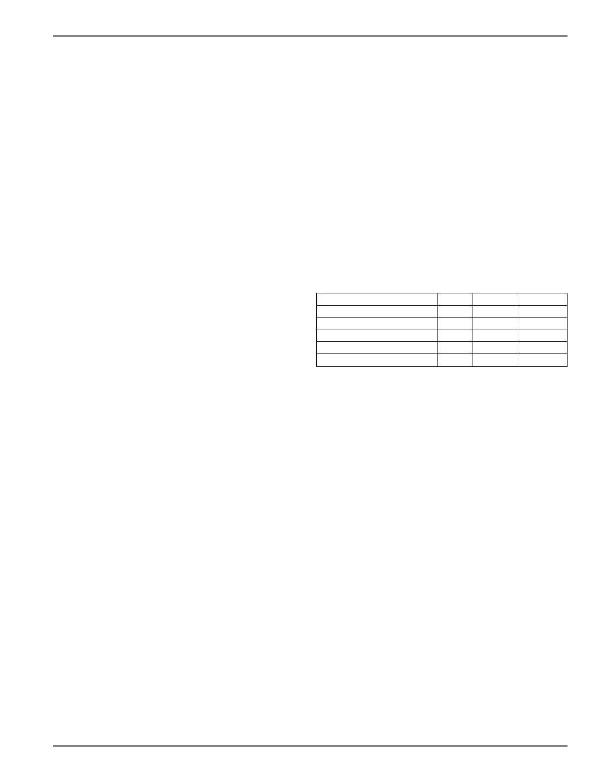
Pump Maintenance Schedule
Make sure the transfer hoses are not “kinked’’. A kinked
hose can cause excessive pump discharge pressure.
Always make sure your hoses are not out of date.
Daily Monthly 3 Months
Lubricate bearings •
Inspect drive coupling •
Clean Inlet Strainer •
Check for leaks •
Inspect hose and ttings •
Bearing Lubrication
NOTICE: AVOID ENTANGLEMENT IN MOVING PARTS.
DO NOT LUBRICATE PUMP BEARINGS, HYDRAULIC
ADAPTER COUPLING OR ANY OTHER PARTS WHILE
THE PUMP IS ACTIVE.
There are two lubrication points in which to grease
the pump bearings; one zerk per bearing cap located
at opposite ends of the pump. Two grease relief and
ventilation fittings have been provided—one at each
end of the pump—to help prevent over greasing the
bearings. Over greasing can cause seal failure if grease
passageways are blocked in some way. Remove relief
fittings or confirm free movement of relief prior to
greasing bearings. Clean each fitting before lubricating
the bearings. This practice helps to prevent foreign
material contamination of the bearings and accidental
over-pressurization of the mechanical seals. Use only
NLGI grade 2 ball bearing grease.
Lubricate ball bearings and hydraulic motor couplings (if
equipped) a minimum of every three months.
Greasing Procedure:
1. Remove grease relief fittings from bearing covers or
hydraulic motor adapter.
2. Grease with a hand gun until grease escapes from
grease relief fitting port.
3. Return grease relief fittings to bearing covers.
9