29
shorten the relay terminal life.
4.3.2 Control Circuit Wiring
The applicable functions in parameter Group E can be assigned to multi-function digital inputs
(S1 to S6), multi-function relay outputs (R1), multi-function analog input (A1) and
multi-function analog output (FM). The default settings are listed in Figure 4.3.1.1 and Figure
4.3.1.2.
For safety, always check the emergency stop operation after wiring. Emergency stop
circuit is necessary to stop the drive immediately in a safe manner to prevent any injuries.
Do not remove the drive covers or touch the circuit boards when the power is on. Failure
to comply could cause electrical shocks to personnel.
Separate control circuit wiring from main circuit wiring and other power lines. Failure to
comply could cause drive malfunction.
Insulate shielded cable with tape to avoid contact with equipment and other signal lines.
Improper insulation could cause drive or equipment malfunction.
Always use shielded twisted-pair cables to prevent drive and equipment malfunction
cause by electrical interference.
Ground the shield to the ground terminal of drive. Failure to comply could cause
erroneous operation or damage to the drive and equipment. Wire ground terminal and
main circuit terminals before wiring control circuit terminals.
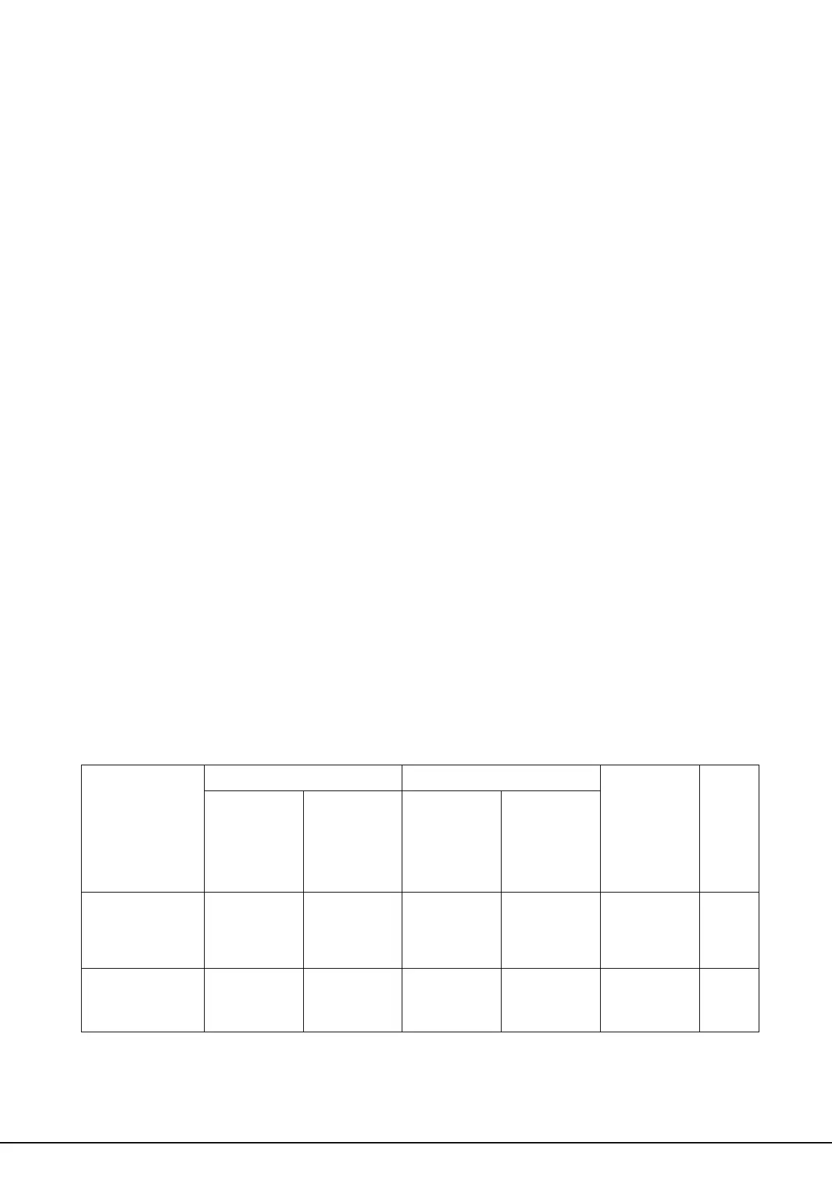
4.3.3 Control Circuit Cable Size and Tightening Torque
Select the cable according to Table 4.3.3.1. Use crimp ferrules on the cable ends for simpler
and more reliable wiring.
Table 4.3.3.1 Cable Size and Tightening Torque
Applicable
Size
mm2
( AWG)
Suggested
Size
mm2
( AWG)
Applicable
Size
mm2
( AWG)
Suggested
Size
mm2
( AWG)
S1, S2, S3, S4, S5,
S6, SC, +V,A1, AC,
FM, PE