6.2 Additional Grounding Connection
•
Ensure that the PE cable is securely connected. Otherwise, electric shocks may
occur.
•
Do not connect the neutral wire to the enclosure as a PE cable. Otherwise, electric
shocks may occur.
•
Good grounding for the inverter helps resist the impact of surge voltage and
improve the EMI performance. Connect the PGND cable before connecting the
AC power cables, DC power cables, and communication cables.
• The PE point at the AC output port is used only as a PE equipotential point, and
cannot substitute for the PE point on the enclosure. Make sure the two terminals
are both grounded reliably.
• It is recommended that silica gel or paint be used around the ground terminal after
the PE cable is connected.
Suggested cable requirement for Ground wires
The additional grounding cable should be of the same cross section as the PE wire in the
AC cable (prepared by customers).
Wiring Connection Procedure
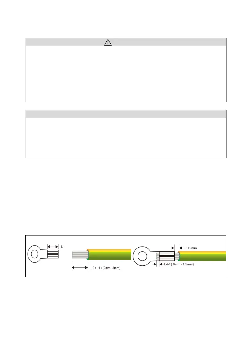
Step1: Crimping an OT terminal.
• Prepare a one-core wire, and remove an appropriate length of the insulation layer
from the PGND cable using a wire Stripper.
• Insert the exposed core wires into the crimping areas of the OT terminal and crimp
them using hydraulic pliers.
Step2: Connecting PE Cable
• Remove the screw on the grounding terminal on the side of the inverter and fasten