Operating manual and inspection booklet
Overview
3532085 89
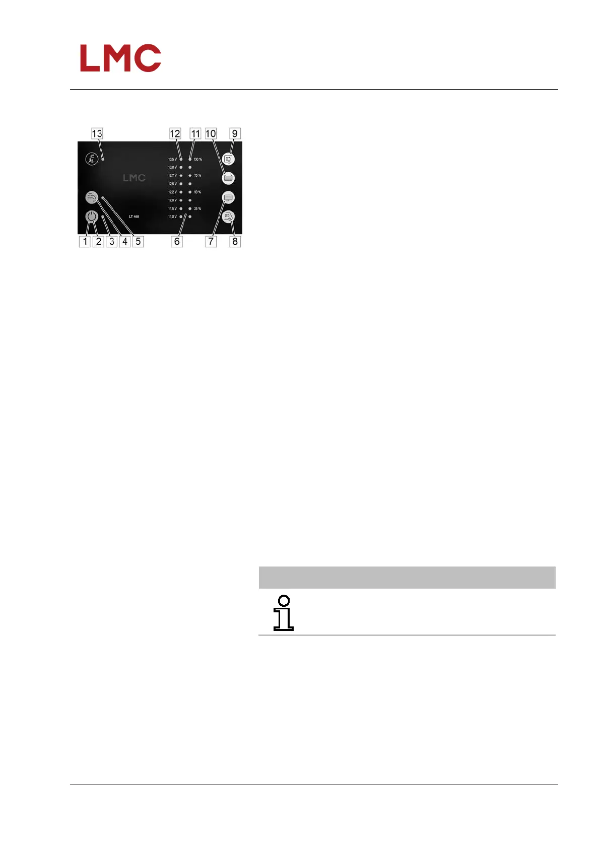
5.4.1.3 Operating and control panel LT 460 A
Fig. 55: Operating and control panel
LT 460 A
The following settings and display options are provided on the
operating and control panel:
1 Sensor buttons
2 Main switch 12 V on/off:
Switching the vehicle’s 12 V supply on and off
3 Main control switch indicator LED (green):
Indicator: 12 V vehicle supply switched on
4 Pump switch:
Switching on or off of the 12 V supply to the water pump
5 Pump switch LED indicator (yellow):
Indicator: Pump supply switched on
6 Indicator elements
7 Query Waste water tank level
8 Query Starter battery voltage
9 Query Living space battery voltage
10 Query Water tank level
11 8 LEDs (blue):
Display of the tank filling levels of water and waste water
tanks in four levels.
12 8 LEDs (2 red - 2 yellow - 4 green):
Battery voltage display in 8 levels and warning of deep
discharge.
13 LED mains power indicator (yellow):
The LED comes on if the mains voltage is switched through
at the input to the vehicle’s mains supply
General information on operating
sensor buttons
The operating and control panel LT 460 A is equipped with
touch-sensitive sensor button fields. These fields react to touch
with a bare finger. If gloves are worn (e.g. when camping during
winter), the operating and control panel LT 460 A cannot detect
the contact. Therefore, gloves must be removed before
operation.
NOTE
For detailed information, refer to the operating
instructions of the relevant manufacturer!