DYNAMIC MOTION SYSTEM - SYSTEM MANUAL // PAGE 16
4.4 ASSEMBLY: SYSTEM WITH MULTIPLE POWER HUBS
This section describes assembly for DYNAMIC MOTION systems with multiple Power Hubs. This congura-
tion can adjust heavy or oversized tables, such as conference tables, without aecting performance. The sys-
tem consists of groups of Actuators. Each Power Hub powers one group of Actuators. Groups are connected
by Sync Cables. The Table Top and Height-Adjustable Columns are supplied by the Reseller.
4.4.1 REQUIRED COMPONENTS
4 to 8 Height-Adjustable Columns with DYNAMIC MOTION Actuators
1 DMLIN Actuator Cable per Actuator
At least 1 User Interface (Handset or other)
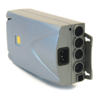
2 to 4 Power Hubs
1 Power Cable per Power Hub
1 to 3 Sync Cables
Optional: Branch Cable for additional connections
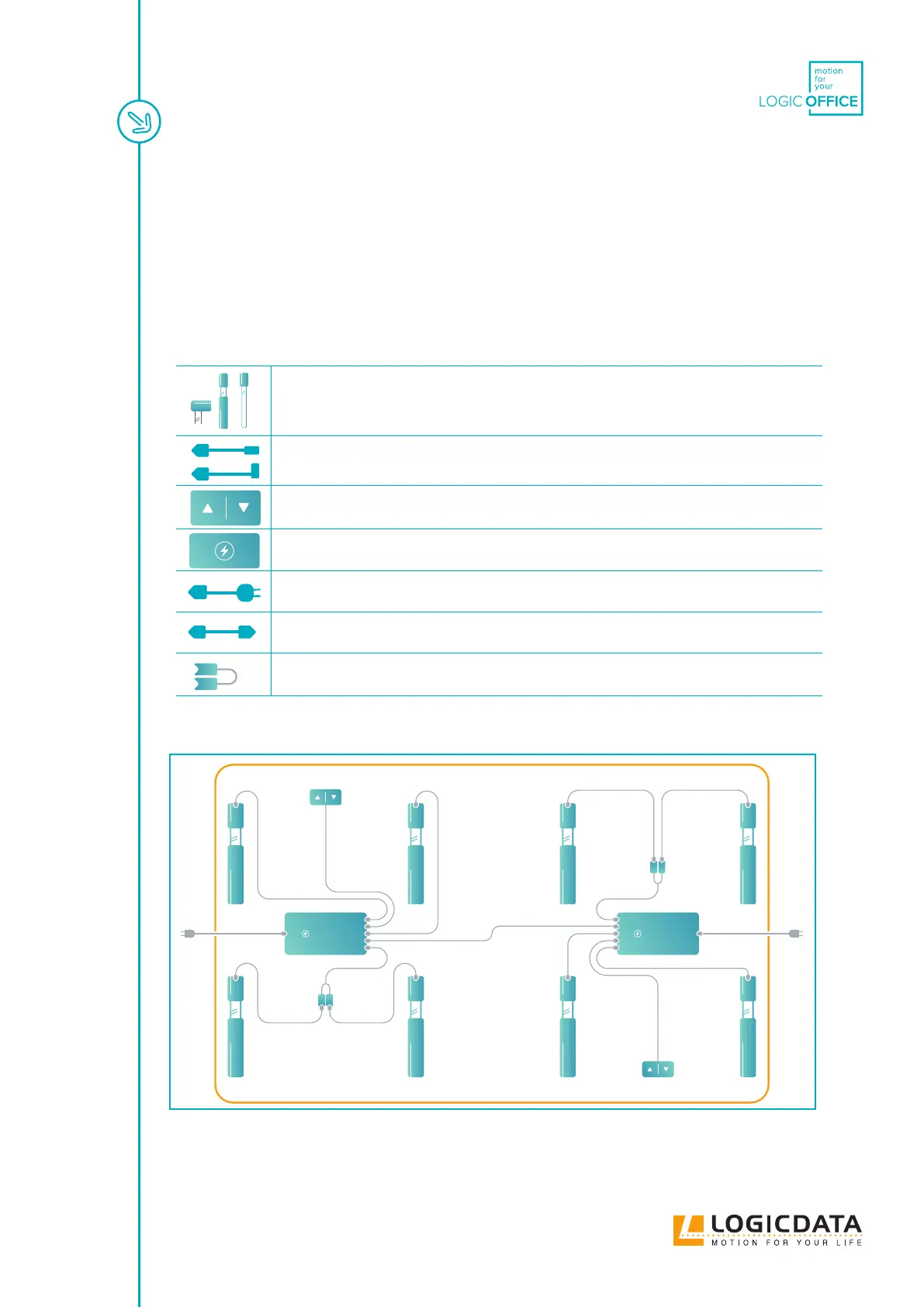
4.4.2 CONNECTING THE COMPONENTS
Fig. 5: Connection map (table system with multiple Power Hubs. 2 Actuator Groups, 8 Height
Adjustable Columns, 2 Power Hubs (DMP360), 2 User Interfaces)
DMP360 DMP360