30
Replacement of Burner Injectors
The gas flow adjustment is made by turning a small screw on the control valves.
Adjusting the Reduced Flame Position
The flame length in the minimum position is adjusted with the bypass screw located on the side of the valve
spindle under the hob controls. The screw must be loosened when changing from LPG to NG.
In changing from NG to LPG, the same screw must be tightened clockwise.
When the flame has a length of at least 4mm, the gas is well distributed. Make sure that the flame does not die
out when passing from the maximum position to the minimum position. Create an artificial wind with your hand
toward the flame to see if the flames are stable.
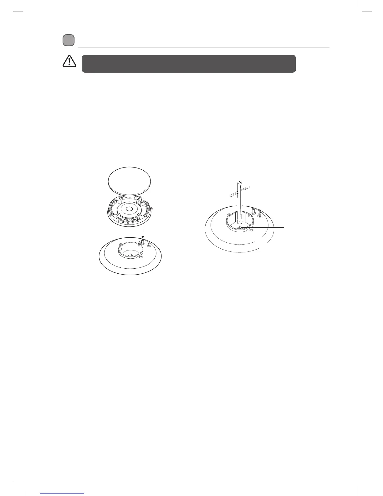
Injector
Spanner
Select the injectors to be replaced according to the “Injector Size Table”.
To Replace the Hob Injectors
• Turn off and isolate the Gas and Electric supplies to the cooker.
• Remove the burner ring and cap.
• Unscrew the injectors. For this, use a 7mm socket spanner.
• Replace the injector with the ones from the conversion set, with the corresponding diameters suitable to the
type of gas that is going to be used, according to the information chart.
Only a suitably qualified and Gas Safe Registered Engineer may change the Hob Injectors.
It is illegal to attempt to change the Hob Injectors yourself.
LFTG90W14_IB.indd 30 09/02/2015 17:51
 Loading...