Logosol Multifunctional Servo Drive LS-231SE
Doc # 712231004 / Rev. A, 05/05/2011
Logosol, Inc. • 1155 Tasman Drive • Sunnyvale, CA 94089 Tel: (408) 744-0974 • www.logosolinc.com
33
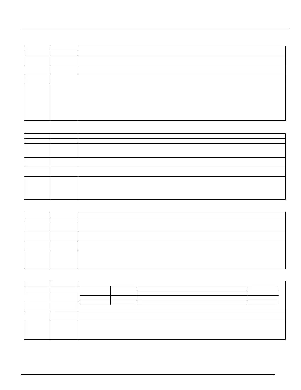
LDCN Single loop mode
MODEbit[C,B,A] = 000
Name Bit Function
DE INbit12 Returns Drive Enable bit (PIC_AE). Bit=‘1’ when PIC_AE bit is SET (Power driver is enabled).
AEN
CN8pin12
INbit7
None dedicated input. Pin=HIGH, Bit=‘1’
Routed to Master encoder Latch strobe (CAP6).
Dir
CN8pin7
INbit14=‘0’ Master encoder counter phase A (CAP4)
Step
CN8pin13
N.A. Master encoder counter phase B (CAP5)
_____
Fault
CN8pin9
N.A.
SW4=OFF HIGH when PIC_AE bit is CLEARED (Power driver is disabled) or NO fault condition is present.
LOW when PIC_AE bit is SET (Power driver is enabled) and fault condition is present.
SW4=ON HIGH when PIC_AE bit is SET (Power driver is enabled) and NO fault condition is present.
LOW when PIC_AE bit is CLEARED (Power driver is disabled) or fault condition is present.
If MODEbitD = 0
Inserted 0.8 µS wide pulse with 51.2 µS period. Used by LS-2311 Master Encoder interface.
If MODEbitD = 1
No pulse. Slave drive Enable output.
LDCN Dual loop mode
MODEbit[C,B,A] = 001
Name Bit Function
DE INbit12 Returns Drive Enable bit (PIC_AE). Bit=‘1’ when PIC_AE bit is SET (Power driver is enabled).
AEN
CN8pin12
INbit7
LOW = Master encoder error.
Routed to Master encoder Latch strobe (CAP6).
Master encoder index rising edge is represented with 0.4 µS wide pulse.
Dir
CN8pin7
INbit14=‘0’ Master encoder counter phase A (CAP4)
Step
CN8pin13
N.A. Master encoder counter phase B (CAP5)
_____
Fault
CN8pin9
N.A.
SW4=OFF HIGH when PIC_AE bit is CLEARED (Power driver is disabled) or NO fault condition is present.
LOW when PIC_AE bit is SET (Power driver is enabled) and fault condition is present.
SW4=ON HIGH when PIC_AE bit is SET (Power driver is enabled) and NO fault condition is present.
LOW when PIC_AE bit is CLEARED (Power driver is disabled) or fault condition is present.
Inserted 0.8 µS wide pulse with 51.2 µS period. Used by LS-2311 Master Encoder interface.
Analog input Single/Dual loop mode
MODEbit[C,B,A] = 010
Name Bit Function
DE INbit12 Returns AEN input (CN8pin12). Pin=HIGH, Bit=‘1’
AEN
CN8pin12
INbit7
0 = Amplifier disabled, fault conditions clear.
1 = Amplifier enable.
Dir CN8pin7 INbit14=‘0’
Master encoder counter phase A (CAP4)
Step
CN8pin13
N.A.
Master encoder counter phase B (CAP5)
_____
Fault
CN8pin9
N.A.
SW4=OFF LOW = fault.
HIGH = NO fault.
SW4=ON LOW when DE is LOW or fault condition is present.
HIGH when DE is HIGH and NO fault condition is present.
Analog input mode with direction invert input
MODEbit[C,B,A] = 011
Name Bit
DE INbit12
AEN
CN8pin12
INbit7
Dir CN8pin7 INbit14
AEN (CN8.12) Dir (CN8.7) Function DE (INbit12)
0 X Amplifier disabled, fault conditions clear. 0
1 0 Amplifier enable. 1
1 1 Amplifier enable, analog input (ADCin) inverted. 1
Step
CN8pin13
N.A. Routed to CAP6.
_____
Fault
CN8pin9
N.A.
SW4=OFF LOW = fault.
HIGH = NO fault.
SW4=ON LOW when DE is LOW or fault condition is present.
HIGH when DE is HIGH and NO fault condition is present.
 Loading...