Logosol Multifunctional Servo Drive LS-231SE
Doc # 712231004 / Rev. A, 05/05/2011
Logosol, Inc. • 1155 Tasman Drive • Sunnyvale, CA 94089 Tel: (408) 744-0974 • www.logosolinc.com
5
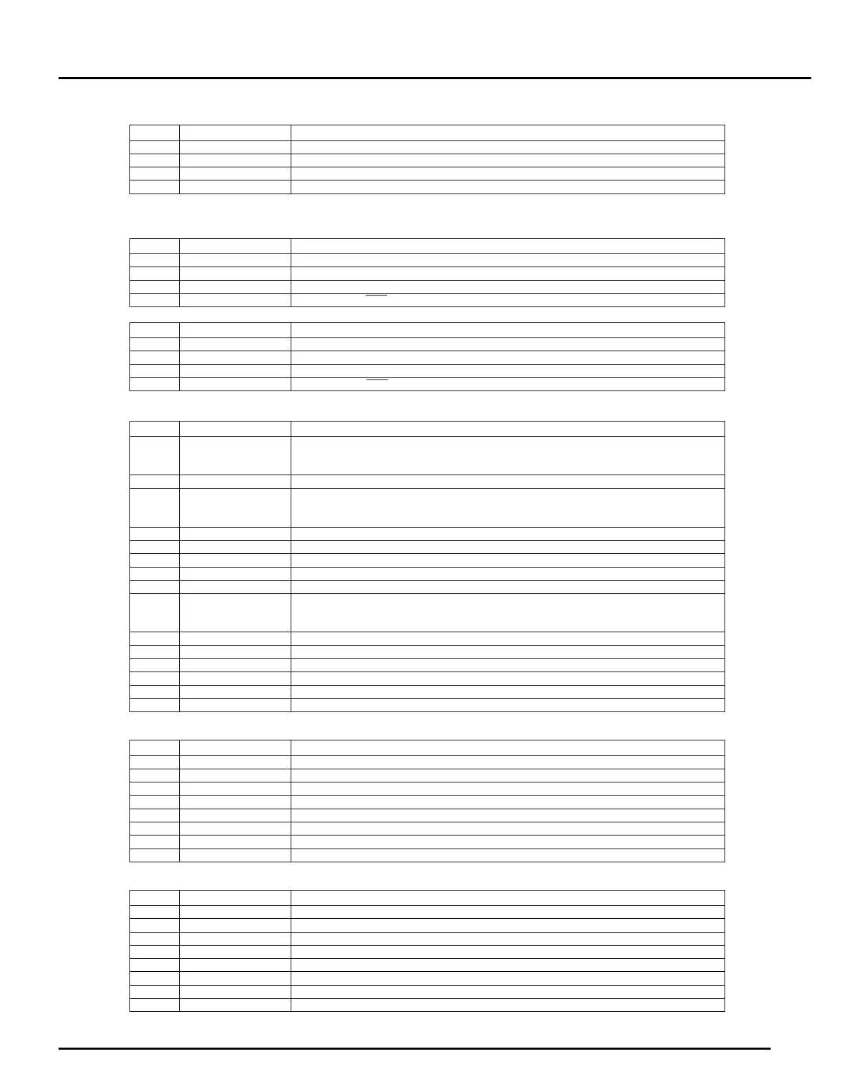
CN2 – I/O
PIN SIGNAL DESCRIPTION
1 Gnd Signal ground
2 Output2 Multifunctional output (mode dependent)
3 Input10 Multifunctional input (mode dependent)
4 Pull-Up Protected power output (+24V)
SAFETY BUS
CN3
PIN SIGNAL DESCRIPTION
1 LIMIT Limit relay contact (CN3)
2 Input9 Limit input
3 FAULT Fault relay contact (CN3)
4 Enable Drive Enable/Stop input
CN4
PIN SIGNAL DESCRIPTION
1 LIMIT Limit relay contact (CN4)
2 Input9 Limit input
3 FAULT Fault relay contact (CN4)
4 Enable Drive Enable/Stop input
CN5 – ENCODER AND COMMUTATOR
PIN SIGNAL DESCRIPTION
1 -Rx/H2
Hall input #2 for brushless motors
Hall data for Panasonic A or S series motors
Not connected for DC motors
2 Enc 5V Encoder +5V power supply
3 -Z/H3
Hall input #3 for brushless motors
Encoder index (-)Z for Panasonic A or S series motors and DC motors with differential
encoder
4 -B/NA Encoder phase (-)B for motors for motors with differential encoder
5 -A/NA Encoder phase (-)A for motors for motors with differential encoder
6 Pull-Up Protected power output (+24V)
7 Limit1 Limit1 input (connected to CN9-4 through 1K resistor)
8 Gnd Signal ground
9 +Rx/H1
Hall input #1 for brushless motors
Hall data for Panasonic A or S series motors
Not connected for DC motors
10 Gnd Encoder ground
11 +Z Encoder index Z
12 +B Encoder phase B
13 +A Encoder phase A
14 HomeIN Home input (connected to CN9-6 through 1K resistor)
15 Limit2 Limit2 input (connected to CN9-2 through 1K resistor)
CN6 –SLAVE
PIN SIGNAL DESCRIPTION
1 N.C. Not connected
2 Gnd Interface ground
3 +Tx (+) Transmit data
4 -Tx (-) Transmit data
5 -Rx (-) Receive data
6 +Rx (+) Receive data
7 -A out (-) Address output
8 +A out (+) Address output
CN7 –HOST
PIN SIGNAL DESCRIPTION
1 +5V RS-232 adapter power supply
2 Gnd Interface ground
3 +Tx (+) Transmit data
4 -Tx (-) Transmit data
5 -Rx (-) Receive data
6 +Rx (+) Receive data
7 -A in (-) Address input
8 +A in (+) Address input