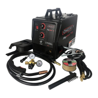
MigWeld™ 100 - 100 AMP MIG Welder 120v
Page 7 of 8
anything with the Torch Handle or an arc may be ignited.
12. Plug the Power Cord into its electrical outlet, presses the Current Switch to appropriate current and turn
the welder ON.
13. Lift the Torch Handle and continue pressing the Trigger until the wire feeds through two inches.
If the wire does not fed, view the Wire Feed Unit and see if the wire is being pushed.
If it is not, turn the welder OFF and add more tension to the Wire Feed Adjusting Spring (36).
14. Turn the welder ON again and press the Trigger.
15. Once the wire is exposed, turn the welder OFF.
16. Slide the Contact Tip over the wire and screw it into Torch Handle.
17. Replace the Nozzle and cut off any excess wire over two inches.
18. Secure the Cover.
NOTE: Duty Cycle: is a welding equipment specification, which defines the number of minutes , within a
10-minute period, during which a given welder can safely produce a particular welding current .
MIGWELD 100 Welder Parts List
Item# Description Qty. Item# Description Qty.
1 Torch 21 Middle Partition Board
2 Contact Tip 22 Overload Indicator Lamp
3 Nozzle 23 Wire Feed Unit
4 Liner 24 Reel Spring
5 Fixing Pole (A) for Gun Body 25 Wing Nut, M6
6 Fixing Pole (B) for Gun Body 26 Reel Locking Knob
7 Switch 27 Wire Reel
8 Cover Locking Spring 28 Reel Holder
9 Knob Cover 29 Self-tapping Screw, ST4.2×25
10 Nut 30 Handle
11 Speed Control Circuit Board 31 Cover
12 Right Side Panel 32 Power Cord
13 Left Side Panel 33 Ground Cable
14 Base Frame 34 Wire Feed Roller
15 Foot 35 Wire Feed Bearing
16 Wire Speed Knob 36 Wire Feed Adjusting Spring
17 Self-tapping screw.ST4.2*13 37 Adjustment Screw
18 Transformer Carriage
38 Face Shield
19 Thermostat 39 Wire Brush/ Hammer
20 Transformer