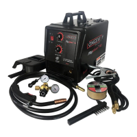
MigWeld™ 100 - 100 AMP MIG Welder 120v
Page 6 of 8
Note: If too much current is drawn from the MIG Welder, the Thermal Overload protector will activate,
the amber indicator will light, and the Arc Welder will turn off until it cools down. If this happens, turn the
Power Switch to the OFF position and wait about 3-5minutes.
9. When the weld is complete, lift the electrode wire clearly away from any grounded object, set the Face
Shield down and turn toward the MIGWELD100 Welder and turn the Power Switch to the OFF
position.
10. Unplug the Power Cord from the electrical outlet.
Maintenance
Caution: Before performing any maintenance on the MIG welder, unplug the Power
Cord from the electrical outlet.
1. Periodically remove the Right and Left side panels (12 and 13), and using compressed Air, blow out all
dust from the interior.
2. Store in a clean and dry location.
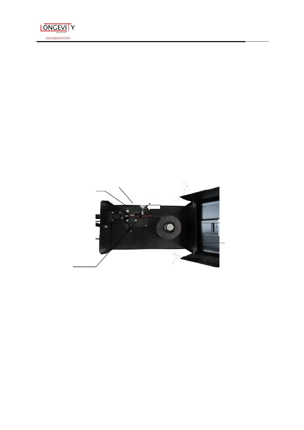
Replacing the Wire Reel
1. Press on the Cover Locking Spring (8), and then lift the Cover (31) using Handle (30) to expose the
Wire Feed Unit (23).
2. Unscrew the Wing Nut (25) and remove the Reel Locking Knob. (26)
3. Remove the empty Wire Reel. (27)
4. Place the new Wire Reel over the shaft and pressed by the Reel Spring (24).
The wire on the reel should unwind counterclockwise (see photo above).
5. Replace the Reel Locking Knob and the Wing Nut. Tighten well.
6. Lift the Wire Feed Adjusting Spring (36) to remove tension.
7. Guide at least 12 inches of wire into the Torch Sheath. If the end of the wire is crimped or bent, cut it
off.
8. Replace tension to the Wire Feed Adjusting Spring (36).
9. Turn the Torch Handle Nozzle Counterclockwise and pull to remove.
10. Turn the Contact Tip counterclockwise and remove.
11. Lay the Torch Sheath out in a straight line so that the wire moves through it easily.
Warning: The following steps require applying power to the welder. Do not touch
Wire Sheath
Tension Adjusting Screw (37)
Handle (30)
Cover (31)
Wire Feed Adjusting Spring (36)