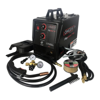
The Longevity MigWeld™ 100 is a 100AMP MIG welder designed for welding sheet metal and light carbon steel. This operating manual provides essential information for safe and effective use, including specifications, safety warnings, assembly instructions, operation procedures, and maintenance guidelines.
Function Description:
The MigWeld™ 100 is a compact and portable MIG welder primarily used for arc welding applications. It utilizes flux-core wire, eliminating the need for external shielding gas, which makes it suitable for outdoor use and simplifies setup. The welder is designed to produce a stable arc for joining various types of sheet metal and light carbon steel, making it ideal for DIY enthusiasts, small workshops, and light industrial tasks. Its core function is to melt and fuse metal pieces together using an electric arc generated between a continuously fed electrode wire and the workpiece.
Important Technical Specifications:
- Rated AC Output:
- Max OCV (Open Circuit Voltage): 22.5 Volts at 80 Amps (20% Duty Cycle)
- Min OCV (Open Circuit Voltage): 20.5 Volts at 60 Amps (20% Duty Cycle)
- Rated AC Input: 120VAC, 60Hz, 18Amps (requires a 20Amps branch circuit)
- Ground Cable: 6AWG, single insulation, 6 feet
- Torch Power Cable: 6AWG, single insulation, 6 feet
- Power Cord: 3-core, double insulated, 14AWG
- Thermal Overload: Both settings: 6 minutes shutdown, 10 minutes back on with light indicator. This feature protects the welder from overheating by automatically shutting it off when too much current is drawn, and then turning back on after cooling.
- Welder Tip: Compatible with 0.030" and 0.040" tips.
- Wire Size: Designed for 0.030"-0.040" flux core wire.
- Wire Spool Size: 4" diameter
- Overall Dimensions: 37 × 21 × 31 cm
- Weight: 15.6 kgs
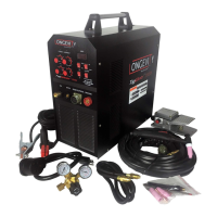
- Accessories Included: 0.040" welder tip, Welding Face Shield, Wire Brush/Hammer Combination.
Usage Features:
The MigWeld™ 100 is designed for user-friendly operation with several key features:
- Control Panel: Features a Wire Feed Speed Knob (16) for adjusting wire feed rate, a Power ON/OFF Switch (7), and a Current Min./Max Switch (7) for selecting welding current. An Overload Indicator Light (22) signals when the thermal overload protector is active.
- Grounding: Requires securely clamping the Ground Cable Clamp (33) to the metal object being welded or to an electrically connected metal workbench to ensure proper grounding and prevent electrical shock.
- Power Connection: Plugs into a dedicated 110VAC, 20amp line with a delayed action type circuit breaker or fuses.
- Arc Ignition: The arc is ignited by pressing and holding the Torch button and stroking the electrode wire against the workpiece. Users are advised not to tap the electrode wire to ignite the arc, as this can damage the electrode's external coating.
- Welding Angle: Once the arc is ignited, the electrode wire should be tilted forward at approximately a 35-degree angle. The wire feeds automatically at a speed dependent on the current setting.
- Safety Precautions: Emphasizes the importance of wearing arc-shaded, impact safety face shields (provided), protective clothing, and avoiding direct viewing of the arc to prevent eye and skin damage. Proper ventilation is crucial to avoid inhaling fumes and gases.
- Extension Cord Usage: If an extension cord is required, it must be of the proper size and type (20amps minimum capability, up to 30 feet, with 12AWG wire size) to prevent overheating and electrical damage. Longer cords require larger wire sizes. Outdoor-rated cords are necessary for outdoor use.
- Duty Cycle: The welder has a specified duty cycle, which indicates the percentage of a 10-minute period during which it can safely produce a particular welding current without overheating.
Maintenance Features:
Regular maintenance is crucial for the longevity and safe operation of the MigWeld™ 100:
- Power Disconnection: Always unplug the power cord from the electrical outlet before performing any maintenance.
- Cleaning: Periodically remove the right and left side panels (12 and 13) and use compressed air to blow out dust from the interior. This prevents accumulation that could lead to overheating or component damage.
- Storage: Store the welder in a clean and dry location to inhibit rust and protect internal components.
- Wire Reel Replacement:
- Press the Cover Locking Spring (8) and lift the Cover (31) using the Handle (30) to expose the Wire Feed Unit (23).
- Unscrew the Wing Nut (25) and remove the Reel Locking Knob (26).
- Remove the empty Wire Reel (27) and place a new Wire Reel over the shaft, ensuring the wire unwinds counterclockwise.
- Replace the Reel Locking Knob and Wing Nut, tightening them securely.
- Lift the Wire Feed Adjusting Spring (36) to remove tension, then guide at least 12 inches of wire into the Torch Sheath. Cut off any crimped or bent wire ends.
- Replace tension to the Wire Feed Adjusting Spring (36).
- Remove the Torch Handle Nozzle and Contact Tip by turning them counterclockwise.
- Lay the Torch Sheath straight to facilitate wire movement.
- To feed the wire, plug in the power cord, turn the welder ON, set the current switch, and press the Trigger until two inches of wire feed through. If the wire does not feed, check the Wire Feed Unit and adjust the Wire Feed Adjusting Spring (36) tension.
- Once the wire is exposed, turn the welder OFF, slide the Contact Tip over the wire, screw it into the Torch Handle, replace the Nozzle, and cut off any excess wire.
- Secure the Cover.
- Professional Service: For safety, a qualified technician should perform regular service and maintenance. Any damaged parts should be properly repaired or replaced by a qualified technician.