The provided document is a multi-language user manual for LORCH TIG welding torches, specifically the a-LTG/a-LTW and i-LTG/i-LTW series. This description will focus on the English sections of the manual to describe the device's function, technical specifications, usage, and maintenance features.
LORCH TIG Welding Torches: a-LTG/a-LTW and i-LTG/i-LTW Series
Function Description
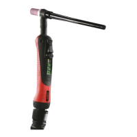
The LORCH TIG welding torches are designed for TIG welding of low and high-alloy materials. They are an integral part of a complete welding system, generating an electric arc for welding in conjunction with a matching LORCH TIG power source. The torches are available in both gas-cooled and water-cooled versions. For water-cooled TIG welding torches, a water circulation cooling unit is mandatory. The i-LTG/i-LTW series torches are specifically designed for use with LORCH welding units featuring Intelligent Torch Control (ITC), while the a-LTG/a-LTW series is compatible with all LORCH TIG welding units.
Important Technical Specifications
The LORCH TIG welding torches are available in power ranges from 80 A to 450 A.
General Torch Data:
- Type of voltage: DC/AC
- DC polarity of electrodes: Usually negative
- Type of use: Hand-held
- Voltage limitation (peak value): 113 V
- Arc ignition voltage and arc stabilization voltage: 12 kV
- Electrode: Tungsten electrodes suitable for TIG use
- Shielding gas: DIN EN ISO 14175 compliant
Electrical Control Devices:
- Switching voltage of button (DC): 0.02 - 12 V
- Switching current of button: 0.01 - 50 mA
- Switching power of button (max.) (resistive load): 0.6 W
Product-Specific Torch Data:
The duty cycle for all models is 35% for AC and 100% for DC.
Electrode diameter ranges vary by model, from 1.0-1.6 mm up to 1.6-6.4 mm.
Torch lengths are consistently 4/8 meters across all models.
Gas Flow Rate:
- Gas-cooled models (a-LTG/i-LTG): Range from 5-12 l/min to 7-18 l/min depending on the model.
- Water-cooled models (a-LTW/i-LTW): Range from 7-20 l/min to 8-22 l/min depending on the model.
Cooling (for water-cooled models):
- Maximum coolant temperature at the inlet of the hose package: 60 °C
- Minimum quantity of cooling flow: 1.0 l/min
- Lowest pressure of entry: 2.5 bar
- Highest pressure of entry: 5.0 bar
- Required cooling unit capacity (min.): 530 W (only in combination with recommended Lorch water cooling equipment)
Environmental Conditions:
- Ambient temperature during welding: -10 ºC to +40 ºC
- Ambient temperature during transport and storage: -25 ºC to +55 ºC
- Relative air humidity: Up to 90% at a temperature of 20 ºC
Usage Features
The TIG welding torches offer different switch modules depending on the desired functionality and the capabilities of the LORCH TIG power source.
Double Button (DD):
- Button 7: Start/Stop the welding process.
- Button 8: Selection of second current (On/Off).
Up/Down (UD):
- Button 9 (Up): Increases welding current.
- Button 10 (Down): Reduces welding current.
Powermaster (PM) (only i-LTG/i-LTW):
- LED 11 (Ampere): Lights up when welding current is displayed (15).
- LED 12 (Job): Lights up when a job is displayed (15).
- Powermaster LED 13: Configurable with free selectable parameters in the welding machine (default: second current I2).
- Powermaster LED 14: Configurable with free selectable parameters in the welding machine.
- Display 15: Shows parameter values.
- Mode Button 16: Switches between parameters LED (11) - LED (14). Pressing for 7 seconds changes the display (15) between right-hand and left-hand mode (a dot at the bottom right indicates left-hand mode). Pressing for 2 seconds unlocks the mode button for 15 seconds (if key lock is activated).
TIG Operation Procedure:
- Follow the specific welding instructions for the task.
- Position the TIG torch at the required start position.
- Ignite the arc using the on/off button.
- Maintain the arc at the start point until a weld pool is established.
- Guide the torch consistently along the entire seam length according to instructions.
- At the end of the seam, or upon completion, stop the welding process by pressing the Start/Stop button.
- Hold the torch in the final position for a few seconds to allow the molten pool to solidify without atmospheric disturbances (shielded by gas flow).
Maintenance Features
Regular and preventive maintenance is crucial for the long life and flawless function of the TIG torch. Maintenance and cleaning should only be performed by qualified and trained personnel. Damaged, deformed, or worn parts must be replaced immediately.
Checks on the TIG Welding Torch:
- All parts should be undamaged and correctly positioned.
- The tungsten electrode and its fastening parts should be undamaged and properly secured.
- If the tungsten electrode surface is no longer smooth and free of grooves, it should be reground.
- Shielding gas flow should be unobstructed, even, and at the required volume.
- The gas nozzle should be in perfect condition, without damage or cracks.
Checks on the Torch Cable Assembly:
- All insulation and cables at the torch connection and power source side should be undamaged.
- All power, coolant, and gas connections to the power source should be clean and securely fastened.
- The outer hose and leather covering should show no external damage (cracks, burn holes).
- The cable assembly should not have kinks that could impede gas or coolant flow.
Tips for Grinding the Tungsten Electrode:
- The surface condition of the electrode significantly influences arc formation, weld bead width, and penetration depth.
- Tungsten electrodes must always be ground longitudinally, with the tip angle depending on the specific welding task.
- The manual recommends the LORCH TEG 4.0 grinding machine, which offers stepless angle adjustment, a diamond grinding plate with central grinding to the central axis, adjustable for diameters up to 4.0 mm, and stepless speed regulation.
Ordering Spare Parts:
- Part numbers for spare and wear parts can be found in current LORCH price lists or obtained from your local LORCH dealer.
Safety Measures:
- Always disconnect the power source before working on torch parts or replacing consumables.
- Avoid inhaling welding fumes and gases, and ensure adequate ventilation or extraction.
- Use appropriate shielding gas (argon or helium) and a pressure reducer.
- Store gas cylinders upright, secured, and away from heat, sparks, or flames.
- Wear appropriate protective clothing, welding shields (EN 175 or EN 379 compliant), and ear protection.
- Ensure the work area is free of flammable materials.
- Do not exceed the maximum connection values or power ratings of the torches to prevent damage or injury.
- Never pull cables over sharp edges or expose them to welding spatter or hot surfaces.
- Do not perform temporary repairs; repairs should be done by qualified personnel.