page 44
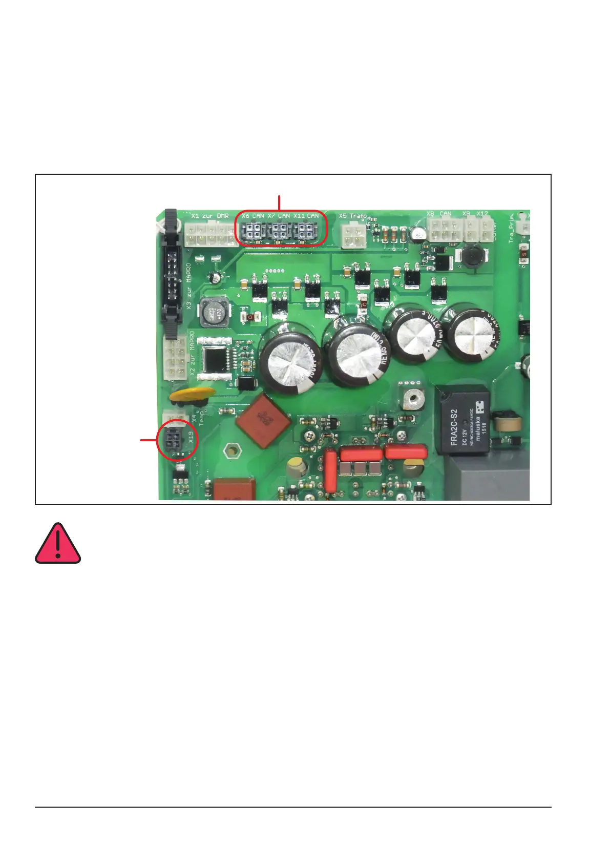
Connection cooling unit
At machines with internal water cooling, the pc-board SF18 was the main control board of the cooling unit. It has a
microprocessor and was connected via the internal CAN-bus (LorchNet) to the pc-board DRV (x6 or X7, X11).
Since September 16th 2015 the pc-board Sf18 was replaced by the pc-board SF24, without microprocessor. it
was still connected to the pc-board DRV, but not to the CAN bus any more. It must be connected to the separate
X19 connector.
Since January 28th 2016 all MicorMIG machine are equipped with a water ow sensor for monitoring the cooling
unit. For this the SF24 was replaced by the SF27. On the pc-board SF27 is a new connector for the water ow
sensor.
Connection SF18 / SF23
Connection
SF24 / SF27
SF37
!! CAUTION !!
It is important not to mix up the connections X19 and X6, this could lead to a damage on the DRV or
SF- pc-board.