page 59
LorchNet-Remote
LorchNet-Remote is the optional remote control interface of the MicorMIG.
It is connected to the power source via the 4-pin socket “LorchNet” at the rear-side, where also the “LorchNet
Connect” can be plugged in.
If the start contact (pins 1 and 2) is closed during the time the machine is switched on, the error message E25-01
is displayed at the front panel.
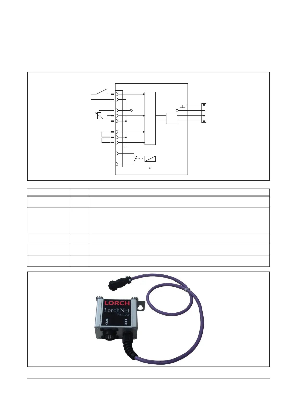
Schematic
+10V
µP
+12V
1
2
3
4
5
6
7
8
9
10
AMP14
CAN
+24V
LorchNet-Remote
1
2
3
4
start
pot.
„external“
„2-T“
I>0
„arc established“
wh
br
gr
ye
signal pin description
start 1 and 2 as soon as pins 1 and 2 are closed, the machine starts the welding process (like pressing the trigger
switch at the torch)
energy setting 4 analog input for setting the welding energy (e.g. via a potentiometer)
0V = min. energy setting of the actual selected welding program
10V = max. setting of the actual selected welding program
! CAUTION : the analog input is only valid, when the identication “external” at the pins 6 and 7 is ac-
tive !
identication “external” 6 as soon as pin 6 is closed to pin 7 (gnd), the analog input (pin 4) is active and the remote control LED
at the front panel is lit
identication “2-T” 8 as soon as pin 8 is closed to pin 7 (gnd), the machine switches automatically to 2-stroke mode (2-T)
when the start signal is given
arc established (I>0) 9 and 10 as soon as welding current is owing, the potential free relay contact is closed
max. contact load: 1A