EasyManua.ls Logo

LOVATO ELECTRIC RGK400SA User Manual

LOVATO ELECTRIC RGK400SA
19 pages
To Next Page IconTo Next Page
Page #1 background imageLoading...
Page #1 background image
Doc: I470GB10_16.docx 18/10/2016 p. 1 / 19
RGK400SA RGK420SA
STAND-ALONE GENERATING SET CONTROLLERS
INSTRUCTION MANUAL
The manufacturer cannot be held responsible for electrical safety in case of improper use of the equipment.
The products illustrated herein are subject to alteration and changes without prior notice. Descriptions and specifications are therefore not contractually binding.
A circuit breaker must be included in the electrical installation of the building. This must be installed near the equipment and within easy of the operator. It must be marked
as the disconnecting device of the equipment: IEC/ EN 61010-1 § 6.12.2.1.
Clean the equipment with a soft cloth; do not use abrasive products, liquid detergents or solvents.
Contents
Page
Introduction 2
Description 2
Functions of front panel buttons and controls
2
Display indications 3
Navigating between the display pages
3
Switching on and starting up (RGK400SA)
3
Switching on and starting up (RGK420SA)
3
Expandability 4
Inputs and outputs 4
User alarms (UAx) 4
IR programming port 4
Parameter setting from PC
4
Parameter setting from smartphone or tablet via Wi-Fi
4
Parameter setting from smartphone or tablet via NFC
4
A
utomatic acquisition of rpm/W ratio
5
Main menu 5
Parameter settings (setup) from front panel
6
Parameter table 6
Programmable input functions
11
Programmable output functions
11
A
larms 12
A
larm table 13
Commands menu 13
Installation 14
Connection diagrams 15
Terminal layout 16
Mechanical dimensions and panel cut-out
17
Technical characteristics
18
Manual revision history
19
CAUTION!
Read this manual before use and installation.
This equipment must be installed by qualified personnel according to applicable standards in order to prevent injury or damage to property.
Before any maintenance operation on the device, disconnect power from all measuring and power supply inputs.
I470GB
10
16 31100301
Question and Answer IconNeed help?

Do you have a question about the LOVATO ELECTRIC RGK400SA and is the answer not in the manual?

LOVATO ELECTRIC RGK400SA Specifications

General IconGeneral
BrandLOVATO ELECTRIC
ModelRGK400SA
CategoryController
LanguageEnglish

Summary

Product Identification

RGK400SA/RGK420SA Controller Identification

Identifies the product models and manufacturer information.

General Information

Instruction Manual and Safety Precautions

Covers the instruction manual title, safety warnings, and cleaning guidelines.

Product Description

RGK400SA/RGK420SA Controller Description

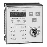
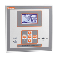
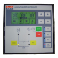
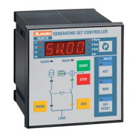
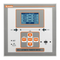
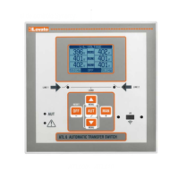
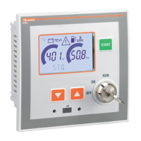
Details the controller's purpose, housing, versions, display, and connectivity.

Front Panel Controls

Functions of Front Panel Buttons and Controls

Explains the operation of buttons and key switch for controlling the generator.

Display and Operation

Display Indications and Navigation

Describes display icons and how to navigate through measurements and pages.

Starting and Stopping

Switching On and Starting Up

Step-by-step procedures for starting and stopping the generator for both models.

Expandability and I/O

Expandability and Inputs/Outputs

Information on expanding capabilities and identification of inputs and outputs.

User Alarms and Programming

User Alarms, IR Port, and PC Programming

Details on user alarms, IR programming port, and PC parameter setting.

Wireless Parameter Setting

Parameter Setting via Wi-Fi and NFC

Using smartphone apps via Wi-Fi or NFC for parameter configuration.

Engine Speed and Menu

RPM/W Ratio Acquisition and Main Menu

Procedure for acquiring RPM/W ratio and accessing the main menu.

Parameter Setup from Front Panel

Setting Parameters from the Front Panel

Steps to access and configure parameters directly from the controller's front panel.

Parameter Table

Parameter Table Overview

Introduction to the parameter table, listing menu codes and descriptions.

Parameter Settings: Utility and General

P01 Utility and P02 General Parameters

Settings related to display, language, system configurations, and voltage transformers.

Parameter Settings: Sensors

P08 Oil Pressure and P09 Coolant Temperature

Configuration parameters for oil pressure and coolant temperature sensors and alarms.

Parameter Settings: Fuel and Start

P10 Fuel Level and P11 Engine Start Parameters

Settings for fuel level monitoring and detailed engine start sequence configurations.

Parameter Settings: Generator Control and I/O

P12 Generator Control, P13 Protection, P14/P15 Digital I/O

Configuration for generator voltage/frequency control, protection, and digital input/output functions.

Miscellaneous, Alarms, and Functions

P17 Miscellaneous, P18 User Alarms, Input/Output Functions

Settings for maintenance, user alarms, and descriptions of programmable input/output functions.

Alarm Reference

Alarm Codes and Descriptions (A01-A37)

Detailed explanations for alarm codes A01 through A37.

Alarm Table Summary

Alarm Table Summary

Table summarizing alarm types and their operational behavior.

Additional Alarms and Commands

Alarms (A38-A47, UA1-UA2) and Commands Menu

Descriptions for additional alarms and list of user-accessible commands.

Advanced Commands and Installation

Advanced Commands (C06-C11) and Installation

Commands for parameter management and controller installation procedures.

Connection Diagrams

Connection Diagrams for Generating Sets

Wiring diagrams for three-phase, single-phase, and two-phase generating sets.

Specific Connection Diagrams

Speed Detection and Battery Charger Wiring

Wiring diagrams for speed detection by pick-up and permanent magnet battery chargers.

Physical Layout and Dimensions

Terminal Layout and Physical Dimensions

Diagrams showing terminal arrangement and physical dimensions for panel mounting.

Technical Characteristics

Technical Characteristics: Power, Inputs, Outputs

Detailed specifications for power, inputs, outputs, and measurement accuracy.

Technical Characteristics: Generator Measurement

Specifications for generator voltmeter and amperometric inputs.

Technical Characteristics: Environment and Approvals

Technical Characteristics: Environment, Connections, Approvals

Specifications for environmental conditions, connections, weight, and type approvals.

Manual Revision History

Record of revisions made to the manual.

Related product manuals