LRAD 500X
11
Voice Boost Switch
The voice boost switch allows the user to boost the level of spoken voice
communications for greater range and intelligibility over distance. When voice boost is
on, music or other non-voice based broadcasts will also be louder, but they will not
sound natural. In situations where excessive reflections cause unnecessary feed back
through the handheld microphone, setting voice boost to the “off” position will alleviate
feedback problems.
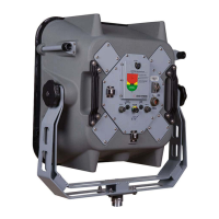
LED Status Indicators
The three indicator LEDs indicate Power, Clipping, and Fault status to the operator.
Power: LED illuminates in green when main power switch is on and
amplifiers are powered up.
Clip: LED illuminates in yellow when input signal is too high. Excessive
input signal level will cause distortion on the output and may damage
the amplifier if applied continuously.
Fault: LED illuminates in red when amplifiers have reported a general fault (over
temperature, over current, or other) and have shut down or failed. Recycling the power
may clear some types of faults.
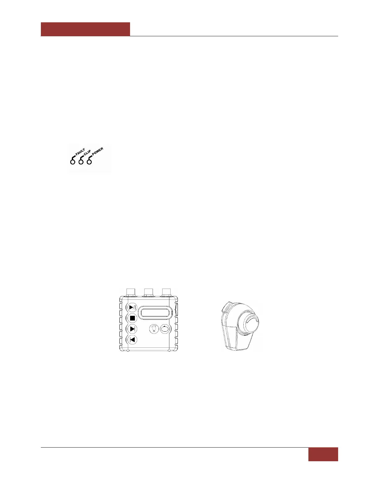
System Setup
The LRAD-500X can be quickly and easily set up with the following steps:
1. Connect the input device(s).
The LRAD-500X ships with a handheld MP3 player device and a handheld microphone. These
input devices are optimized for use with the LRAD-500X, although alternate devices may be
connected as well.
These input devices include the connectors required to attach to the LRAD-500X. There are two
holding clips on the rear panel that allow for the microphone and MP3 player to be stored on
the rear of the unit for easy access.
2. Mount the unit.
The LRAD-500X unit alone can rest on a flat surface such as the roof of a vehicle with the feet
that are built into the base of the unit. Optionally, the unit can be installed in a yoke, tripod
mount, ship-rail mount, or Humvee mount, all of which are available from ATC. The LRAD-500X
includes three hardened structural mounting points that can be used to attach to other
mounting devices. The relevant dimensions and locations of these mounting points are given in
the following figure.