EasyManuals Logo

LS SV150iS5-4 User Manual

Default Icon
205 pages
To Next Page IconTo Next Page
To Previous Page IconTo Previous Page
Page #175 background imageLoading...
Page #175 background image
Chapter 7 - Options
169
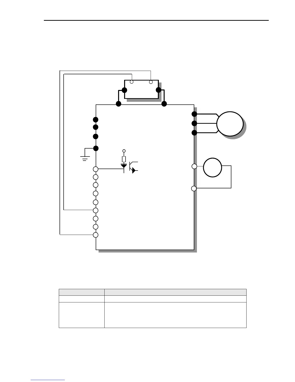
3) DB Resistor Wiring
When wiring, connect the DB Resistor as SHORT as possible.
· DB resistor wiring for 1 – 5 HP Inverter
DB resistor terminal Terminal description
B1, B2 Connect the DB Resistor to Inverter terminal B1, B2.
TH1, TH2
Thermal sensors provided with the DB resistor.
P1 is ON (TH1-TH2 Shorted) at normal (ambient temp) and P1 is OFF (TH1-TH2
Open) at overheated status. Connect the thermal sensor to one of the multi-function
input (P1, P2 or P3, I/O 12-14 setting: Ext Trip-B).
IM
U
V
W
G
R
S
T
B2
DB
Resistor
FX
RX
BX
RST
JOG
P2
P3
FM
+
FM
5G
Analog freq
output
2)
(0-10V)
P1
REV Run / Stop
FWD Run / Stop
Fault Reset
Jog
Max Current thru
PC: 5mA
CM
24 V
TH1
TH2
Max distance between inverter and
DB Resistor: 5m
Multi-function input terminal
(I/O-12 Setting: Ext Trip-B)
B2
B1
B1

Questions and Answers:

Question and Answer IconNeed help?

Do you have a question about the LS SV150iS5-4 and is the answer not in the manual?

LS SV150iS5-4 Specifications

General IconGeneral
BrandLS
ModelSV150iS5-4
CategoryController
LanguageEnglish

Related product manuals