Fitted Options- Power Supply: 24V Output Option Card: 1-Current 2-Relays Channel1: Cond Channel2: Cond Channel3: Cond
Mains 3-Current 0-Relays pH/Redox pH/Redox pH/Redox
3-Current 4-Relays ECS ECS ECS
5-Current 2-Relays DO DO DO
Modbus 4-Relays Aux mA IP Aux mA IP Aux mA IP
SS SS SS
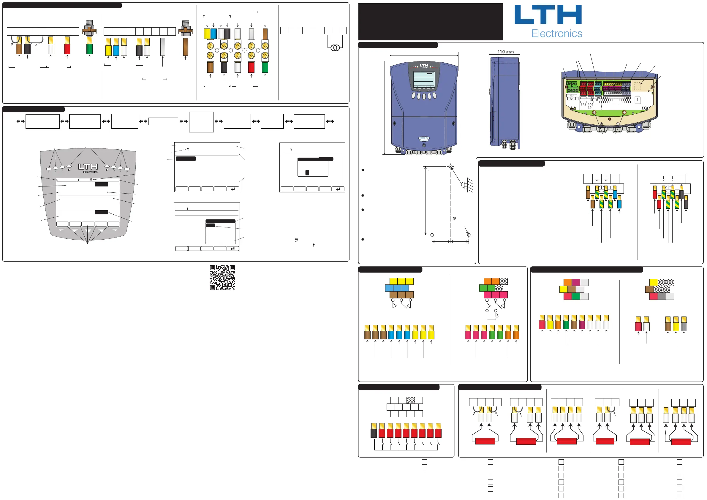
MXD75
Quick Start Guide
Relay Connection Details
MXD75 Instrument Dimensions
Chaul End Lane
Luton
Bedfordshire
LU4 8EZ
England
Telephone: +44 (0)1582 593693
Fax +44 (0)1582 598036
Email: sales@lth.co.uk
Web: lth.co.uk
74 mm
300 mm
6 mm x
3 o
8 mm
74 mm
Power Connection Details
CAUTION!
Always remove the main power from the
system before any alterations to the wiring.
Ensure that both power lines are isolated. Make
sure that the power cannot be switched on by
accident whilst the instrument is being
connected. For safety reasons an earth
connection must be made to the earth terminal
of this instrument.
Local wiring and safety regulations should be
strictly adhered to when installing this
instrument. If the installation methods and
cable types recommended in this guide are
followed, then the instrument will achieve the
levels of EMC protection as specied in the
appropriate manual.
Consult the serial label on the side of the
instrument for supply voltage requirements.
Power Supply
“Live” In
Power Supply
“Live” Out
(For Daisy Chaining)
Power Supply
“Neutral” In
Power Supply
“Neutral” Out
(For Daisy Chaining)
Protective Earth
(Must Be Connected)
Earth
L
+
N
-
L
+
N
-
Earth
Earth
Power Connector
85V-265V AC/DC Power Supply
Connection Details
Power Supply
“+” In
Power Supply
“+” Out
(For Daisy
Chaining)
Power Supply
“-” In
Power Supply
“-” Out
(For Daisy
Chaining)
Protective Earth
(Must Be Connected)
Earth
L
+
N
-
L
+
N
-
Earth
Earth
Power Connector
18V-32V AC/DC Power Supply
Connection Details
Relay Connection Details
Available Relays Vary Depending On Instrument Conguration
5-6
NO3 C3 NC3
NO2 C2 NC2
NO1 C1 NC1
NO6C6
NO5C5
NO4 C4 NC4
Relay 1
Normally
Open
Contact
Relay 1
Common
Contact
Relay 1
Normally
Closed
Contact
Relay 2
Normally
Open
Contact
Relay 2
Common
Contact
Relay 2
Normally
Closed
Contact
NO1 C1 NC1 NO2 C2 NC2 NC3NO3 C3
Relay 3
Common
Contact
Relay 3
Normally
Open
Contact
Relay 3
Normally
Closed
Contact
Relay 4
Normally
Open
Contact
Relay 4
Common
Contact
Relay 4
Normally
Closed
Contact
Relay 5
Normally
Open
Contact
Relay 5
Common
Contact
Relay 6
Normally
Closed
Contact
NO4 C4 NC4 C5 NO5 C6 NO6
Relay 6
Normally
Open
Contact
Relays 1 - 3 Connector Relays 4 - 6 Connector
LTH recommends using No.
10 x 1¼ inch round head
screws or similar for
mounting.
Ensure top screw head is 8
mm proud.
Care must be taken when
tting the unit on uneven
walls or surfaces. Do not
over stress the mounting
lugs.
Over tightening the
mounting screws could also
break the lugs.
Drill Hole Dimensions
SKT5
SKT6
SKT7
HEADER A
HEADER B
HEADER C
HEADER D OR E
COMMS A
COMMS B
CH3
CH2
CH1
85-250V 15W
_
~
1 4 7
2
5
8
3
6
G
G
G
DIGITAL
INPUTS
SENSOR INPUT 3
SENSOR INPUT 2
SENSOR INPUT 1
L
+
N
-
L
+
N
-
SD CARD
LINK
ACT
0/4-20 mA
OUTPUT
1
2
A+ -
A
A B
B
G
E
C
A
+
-
+
-
E E
R
R
A
B
B
A
A
B B
+
-
+
-
R R D
D
CONDUCTIVITY
PH / REDOX
ECS CONDUCTIVITY
5-6
A+
B+
C+
D+
-
-
-
0/4-20 mA
OUTPUTS
3
2
1
6
5
4
F1
F2
F3
F4
F5
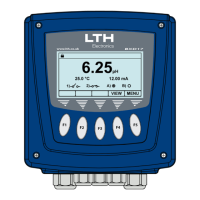
09:56
MON 1 JUN 2009
CH1:
517.2
µS/cm
i)
ii)
12.3
°C
A: 12.28mA
CH2:
9.64 pH
i)
ii)
25.0
°C
-156mV
CH3:
23.3 %
i)
ii)
28.0
°C
2.15Atm
MENU
CAL
242 mm
331 mm
TANK 1
110 mm
CH3
CH2
CH1
85-265V 15W
_
~
1 4 7
2
5
8
3
6
G
G
G
DIGITAL
INPUTS
SENSOR INPUT 3
SENSOR INPUT 2
SENSOR INPUT 1
L
+
N
-
L
+
N
-
SD CARD
0/4-20 mA
OUTPUT
1
2
A+ -
A
A B
B
G
E
C
A
+
-
+
-
E E
R
R
A
B
B
A
A
B B
+
-
+
-
R R D
D
CONDUCTIVITY
PH / REDOX
ECS CONDUCTIVITY
5-6
A+
B+
C+
D+
-
-
-
0/4-20 mA
OUTPUTS
3
2
1
6
5
4
Power Supply
Input
Relays
Current Outputs
/ Modbus RS485
Channel 1
Input
Channel 2
Input
Channel 3
Input
Digital
Inputs
SD Card
Slot
Earth Studs
Ethernet
Port
(Future
Expansion)
Exact Instrument Conguration Depends
Upon Ordered Specication
MON 1 JUN 2009
09:56
CH1: 517.2 µS/cm TEMP1: 12.3°C
CH2: 9.64 pH
CH3: 23.3%
TEMP2: 25.0°C
TEMP3: 28.0°C
MAIN MENU
DIGITAL INPUTS
CHANNELS
EXIT
4-20mA OUTPUTS
CALIBRATION
SETPOINT / RELAYS
CONFIGURATION
CURSOR
FURTHER MENU
PAGES BELOW
INSTRUMENT
READINGS
CURRENT
DATE / TIME
UNIT STATUS
FURTHER MENU
PAGES ABOVE
MON 1 JUN 2009
09:56
CH1: 517.2 µS/cm TEMP1: 12.3°C
CH2: 9.64 pH
CH3: 23.3%
TEMP2: 25.0°C
TEMP3: 28.0°C
SETPOINT 1 SETUP
INPUT SOURCE:
RANGE:
TRIGGER:
HIGH VALUE:
MODE:
CHANNEL:
SENSOR
0 to 9.999 mS/cm
HIGH
7.500mS/cm
ON/OFF
EXIT
CHANNEL 1 (COND)
LOW
BAND
LATCH HIGH
TRIGGER
HIGH
LATCH LOW
CURSOR
ADDITIONAL
OPTIONS BELOW
OPTION POP-UP
MON 1 JUN 2009
09:56
CH1: 517.2 µS/cm TEMP1: 12.3°C
CH2: 9.64 pH
CH3: 23.3%
TEMP2: 25.0°C
TEMP3: 28.0°C
CHANNEL 1 SETUP
UNITS:
CELL CONSTANT:
RANGE:
TEMP INPUT SENSOR:
TEMPERATURE UNITS:
MODE:
SIEMENS(S/cm)
1.000
AUTO
PT1000
°C
EXIT
ON-LINE
SECURITY CODE
CODE
ENTER ACCESS
* * *
0
User Interface Overview
Scrolling Menu Layout
Front Layout
Main Menu Layout
Pop-Up Option Layout
Security Access Pop-Up
To protect the instrument setup
from unauthorised or accidental
tampering, a security access code
system is present. This is
implemented via the instrument’s
menu system which operates in two
modes, “locked” as indicated by a
padlock symbol and “unlocked” as
indicated by a key symbol.
Part No. 6127
Eighth Issue February 2019
Copyright LTH Electronics Ltd.
The default Access Code is: 1000
09:56
MON 1 JUN 2009
CH1:
517.2 µS/cm
i)
ii)
12.3°C A:12.28mA
CH2:
9.64 pH
i)
ii)
25.0°C -156mV
CH3:
23.3 %
i)
ii)
28.0°C 50.15 µS/cm
MENUACK
DOSE ALARM
CAL
CURRENT DATE
UNIT STATUS
CURRENT TIME
CHANNEL
MESSAGES
CHANNEL SECONDARY
READING ii
CONTEXT SENSITIVE BUTTON FUNCTIONS
CHANNEL PRIMARY
READING
CHANNEL ID
CHANNEL SECONDARY
READING i
CHANNEL ALARM
STATUS
SETPOINT STATUS
LEDS
SETPOINT STATUS
LEDS
ALARM STATUS
LEDS
TANK 1
TANK 3
CHANNEL
LABEL
Front Screen
Current
Output
Bargraphs
Channels
Setup
Setpoint /
Relays Setup
4-20mA
Outputs Setup
Digital
Inputs Setup
Error
Messages
Live Trends
1, 2 & 3*
*Optional Extra
For conguration and calibration information please consult
the operational manuals available online at -
lth.co.uk/index.php/downloads/ or via the adjacent QR code.
A+
C+
D+
E+
F+
-
-
-
0/4-20 mA
OUTPUTS
B+
Current Output Connector
Current
Output A+
Current
Output B+
B+ C+ D+ E+ F+
Current
Output D+
Current
Output -
(Common)
Current
Output E+
Current
Output C+
Current
Output F+
Current
Output -
(Common)
Current Output Connection Details
A+
-
-
-
Current
Output -
(Common)
Current Output & Modbus Connection Details
-
MODBUS RS485
& 0/4-20 mA OUTPUT
Modbus and Current Output Connector
Current
Output A+
Current
Output -
(Common)
Modbus A
Conenction
(Inverting)
(Rx-/Tx-)
Modbus B
Connection
(Non-Inverting)
(Rx+/Tx+)
Modbus and Current Output
Connection Details
A+
mA
Modbus C
Connection
(0V Reference)
Optional
-
mA
A-
485
B+
485
C
G
485
A+
mA
A-
485
B+
485
CG
485 mA
Available Current Output and Modbus Connections Vary Depending Upon
Instrument Conguration
Digital Input Connection Details
G 1 2 3 4 5 6 7 8
Digital Input Connector
1 4 7
2
5
8
3
6
G
G
G
Digital Input Connection Details Temperature Connection Details
Sensor Input Connector
Link
Link
RTD
2 Wire RTD
Connection
A
A
B
B
Sensor Input Connector
RTD
3 Wire RTD
Connection
Link
A
A
B
B
Sensor Input Connector
RTD
4 Wire RTD
Connection
A
A
B
B
Smart Input Card
Connector
Link
RTD
2 Wire RTD
Connection
A
B
B
RTD
4 Wire RTD
Connection
A
B
B
Smart Input Card
Connector
Not
Connected
RTD
3 Wire RTD
Connection
A
B
B
Smart Input Card
Connector
Standard Dissolved Oxygen Input Card Connection Details
Dissolved Oxygen Input Connector
A
A
B
B
T
C
A
A
P
g
p
Instrument
Earth Stud
A
Brown
B
Black
Anode
Red
Broadley James ProcessProbe™ Polargraphic
Dissolved Oxygen Sensor Cable
Connection Details
Cathode
White
Link
Link
Green
(Outer Screen)
Sensor Input
Temperature Input
Anode
(White Core
Screen)
54D Extension Cable
Sensor Input
Yellow Blue White Black
Temperature Input
Cable
Outer
Screen
Cathode
(White Core)
“TC”
(Black)
“CATH”
(White)
“ANOD”
(Red)
“TC”
(Brown)
Green
Temperature Input Sensor Input
Broadley James ProcessProbe™ Sensor Cable
Broadley James ProcessProbe™ Cable To
54D Extension Cable Connection Details
Pressure Transmitter
Connection Details
Dissolved Oxygen Input Connector
-+
4-20mA
A
A
B
B
T
C
A
A
P
g
p
Anode
(White Core
Screen)
WhiteYellow
54D Extension Cable Connection Details
Cable Outer
Screen
Cathode
(White Core)
Sensor Input
Temperature Input
Blue
Black
Dissolved Oxygen Input Connector
A
A
B
B
T
C
A
A
P
g
p
Instrument
Earth Stud