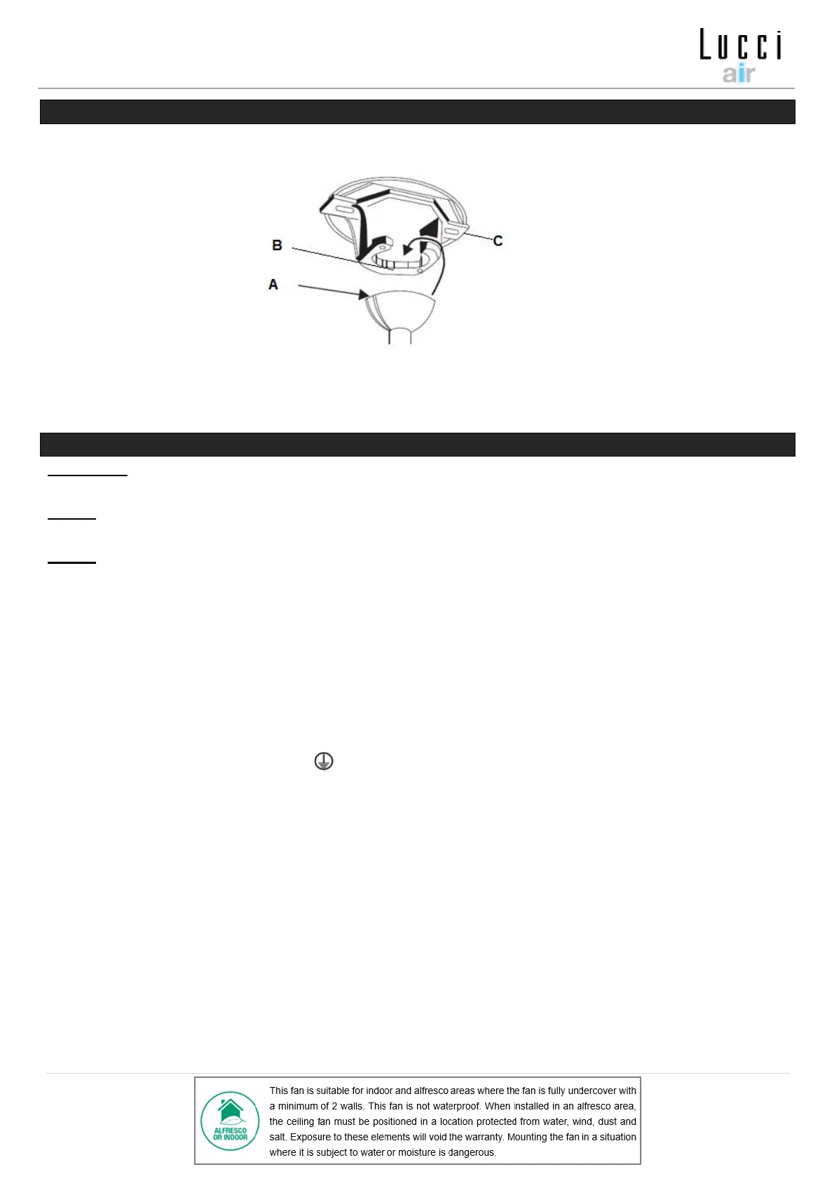
HANGING THE FAN
Lift the fan assembly onto the mounting bracket. Ensure the key slot (A) of the hanger ball is positioned on
the key pin (B) of the mounting bracket (C) to prevent the fan from rotating when in operation. (Fig. 6)
ELECTRICAL WIRING DIAGRAM THE FAN
WARNING: FOR YOUR SAFETY ALL ELECTRICAL CONNECTIONS MUST BE UNDERTAKEN BY A
LICENSED ELECTRICIAN.
NOTE: AN ADDITIONAL ALL POLE DISCONNECTION SWITCH MUST BE INCLUDED IN THE FIXED
WIRING.
NOTE: IF THERE ARE TWO OR MORE DC CEILING FANS INSTALLED IN THE ONE LOCATION, AN
ISOLATION SWITCH IS REQUIRED FOR EACH CEILING FAN. THIS IS REQUIRED WHEN
PROGRAMMING THE REMOTE AND RECEIVER TO PAIR TOGETHER.
Note: If a down rod extension is used, the Light kit extension cable (item 9, of Fig.1) is required.
See Fig. 8 for instructions below to wire up the fan.
• Connect “LIVE” supply wire to the “L” of terminal block on the mounting bracket.
• Connect “NEUTRAL” supply wire to the “N” of terminal block on the mounting bracket.
• Connect “EARTH” wire to the “ ” of terminal block on the mouthing bracket.
• Hang the fan (Refer to “hanging the fan” Fig. 6, page 6).
• Plug connector from the supply wiring from the mounting bracket to the input of the DC motor
driver/receiver.
• Plug the light connector and the fan connector from the DC motor driver/receiver to the input wires of
the fan motor and the light kit.
• Carefully insert the Remote Receiver above the hanger ball in the remainder spacing in the mounting
bracket. Take care not to damage or loosen any of the wiring. (Fig. 8).