Lucent Technologies Galaxy Power System 4812
Issue 5 June 2000 Troubleshooting Preparations 12 - 9
Reference Figures, continued
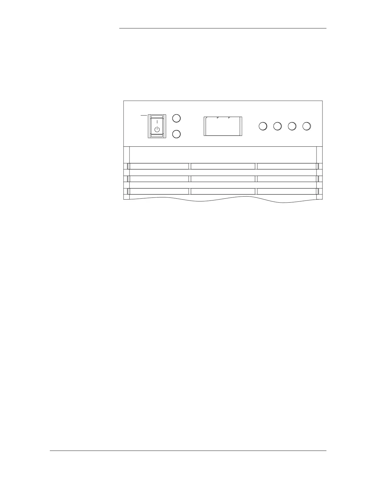
Rectifiers During normal operation, the rectifier’s green ON LED will be lit and
the display will show the rectifier’s output current.
Figure 12-6: Rectifier Display
ID
ALM
ON
STBY
LIM FAN
ALM
BST