Assembly
16 Snow depth sensor SHM 31, V2.1
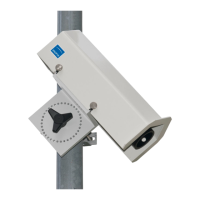
Figure 13: Assembling the connection cable on the sensor. The
strain relief sleeve is inserted into the recess in the base plate
during cable assembly. The angle of the Amphenol connector can
be adjusted (in increments of 45°) as needed once the mounting
ring has been loosened.
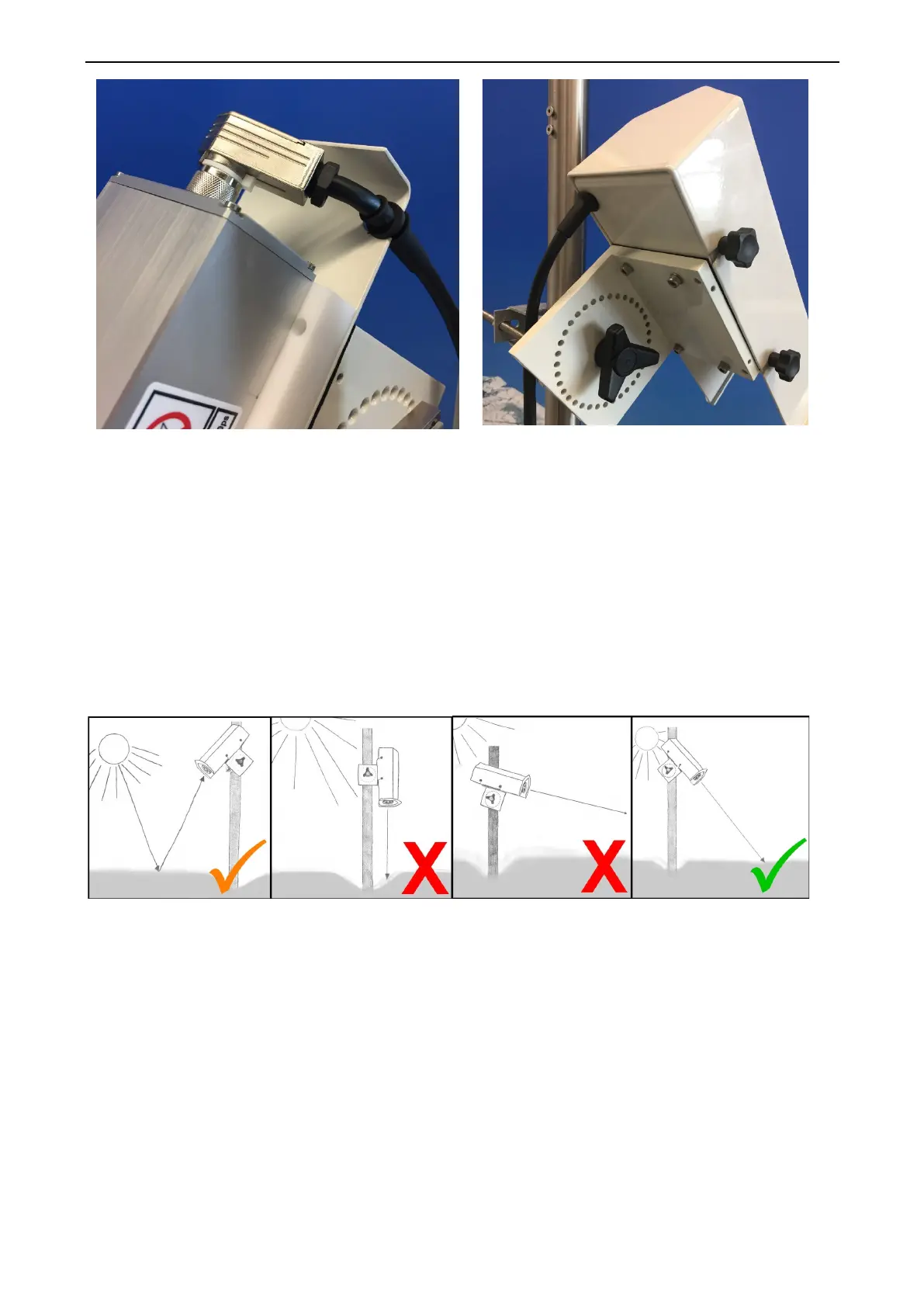
Figure 14: Sensor assembled with hood. After attaching the
cable, the weatherproof protective hood is fixed again using
the three knurled screws.
T
he sensor can be placed on the pins of the mast clamp by means of its 360° perforated ring and locked in
place using the tristar knob. The perforated ring has a 10° grading and enables rough adjustment of the
sensor tilt.
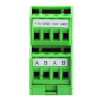
Figure 15 shows the general installation conditions. The criterion of not aligning the sensor towards the sun
has been softened somewhat with the SHM 31, since no restrictions have yet been established regarding the
radiation power due to sunlight reflected on the snow’s surface. However, higher measurement uncertainties
cannot be ruled out where there is strong solar radiation in the high mountains.
Figure 15: Assembly direction and angle of the SHM 31
U
nlike the SHM 30, the angle of the SHM 31 no longer has to be measured manually and transferred to the
sensor. The SHM 31 has a built-in tilt sensor.
In the delivery state, the reference angle is used to calculate the snow depth. The reference angle is
determined after installation along with the reference height during the zero measurement. However, the
current angle can also be used for the calculation. The corresponding measurement channels for the angles
are listed in the list of UMB channels in this manual.