Operating Manual V25/09.2019
Ventus / Ventus-X / V200A
Chapter 10 Connections 18
10 Connections
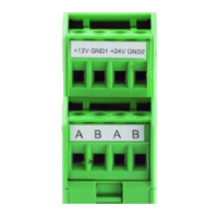
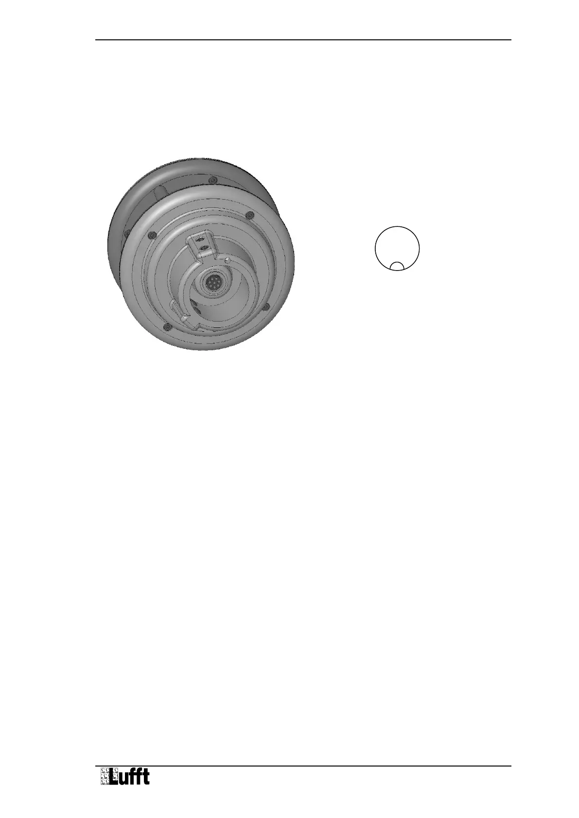
There is an 8 pole screw connector on the underside of the equipment. This serves to connect
the supply voltage and interfaces by a connection cable.
Equipment connector:
Figure 7 Connections
Pin assignment full duplex:
1 Y Serial interface RXD- pink
2 B Serial interface TXD- yellow
3 Control connection red
4 Z Serial interface RXD+ grey
5 A Serial interface TXD+ green
6 Analog ground blue
7 Supply voltage - white
8 Supply voltage + brown
Pin assignment half duplex/analog interface:
1 Analog interface A pink
2 B Serial interface RXD/TXD- yellow
3 Control connection red
4 Analog interface B grey
5 A Serial interface RXD/TXD+ green
6 Analog ground blue
7 Supply voltage - white
8 Supply voltage + brown
Pin assignment SDI-12 interface:
1 - pink
2 SDI-12 Data yellow
3 SDI-12 activation red
4 - grey
5 green
6 SDI-12 GND and SDI-12 activation blue
7 Supply voltage - white
8 Supply voltage + brown
View on cable socket solder
connection
 Loading...