Operating Manual V25/09.2019
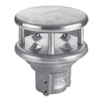
Ventus / Ventus-X / V200A
Chapter 10 Connections 19
(for SDI12 connection please always follow the detailed notes in Chap. 10.7)
The connection cable screen must NOT be laid to ground in the control panel for
Ventus
!
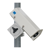
The
Ventus
will be earthed through the screws with the earthed mast .
The connection cable screen MUST be laid to ground in the control panel for V200A !
If the equipment is not connected correctly
- It may not function
- It may be permanently damaged
- The possibility of an electrical shock may exist under certain circumstances
10.1 Supply Voltage
The supply voltage for
Ventus
is 24V DC ± 10%. The power supply unit used must be approved
for operation with equipment of protection class III (SELV).
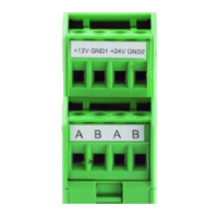
10.2 RS485 Interface
The equipment has an electrically isolated RS485 interface for configuration, measurement
polling and the firmware update.
The RS485 interface is designed as optionally half or full duplex, 2 or 4 wire connection.
The following operating restrictions exist depending on the half or full duplex operation setting:
Autonomous telegram transmission is
possible
No autonomous telegram transmission
possible
Transmission of values via current output is
not possible
Transmission of values via current output is
possible
Heating control via control pin is possible
Heating control via control pin is possible
Triggering of NMEA telegram transmission
over Control-PIN is possible
Triggering of NMEA telegram transmission
over Control-PIN is not possible
Firmware update not possible
Restrictions in full and half duplex operation
See page 32 for technical details.
10.3 Analog Interface Circuits
2 analog interface circuits are provided for analog data transmission. Both are updated every
250ms.
Interface A can be configured for 0 or 4-20mA current output, 0 or 2-10V voltage output as well
as for frequency output in the range from 2 – 2000Hz (with adjustable voltage level up to 10V)
Note: For the use of the analog outputs the serial communication protocol must be set to UMB
binary!
Interface B can be configured for 0 or 4-20mA current output and 0 or 2-10V voltage output
The channels to be transmitted by way of these interfaces can be adjusted with the aid of the
UMB-Config-Tool. The default values are Channels 400 (current wind speed in m/s (A)) and 500
(current wind direction (B)).
The scaling of the outputs is also adjustable.
The maximum load on the current output is 300 .
1
Factory setting