Operating Manual V25/09.2019
Ventus / Ventus-X / V200A
Chapter 21 List of Figures 74
21 List of Figures
Figure 1: Measurement Sections........................................................................................................................................ 7
Figure 2 Influence of Wind on Time of Flight ...................................................................................................................... 8
Figure 3 Fastening to the Mast ..........................................................................................................................................14
Figure 4 North Markings ....................................................................................................................................................15
Figure 5 Alignment to North ..............................................................................................................................................15
Figure 6 Installations Sketch .............................................................................................................................................17
Figure 7 Connections ........................................................................................................................................................18
Figure 8 Connection to ISOCON-UMB ..............................................................................................................................20
Figure 9: Sensor selection .................................................................................................................................................23
Figure 10: Device settings .................................................................................................................................................24
Figure 11: Communication Parameters ............................................................................................................................25
Figure 12: Heating Parameters .........................................................................................................................................26
Figure 13: Wind Parameters .............................................................................................................................................26
Figure 14: Analog Outputs ................................................................................................................................................27
Figure 15: Channel list ......................................................................................................................................................29
Figure 16: Data query ........................................................................................................................................................30
Figure 17: Drawing
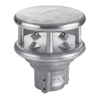
Ventus
.................................................................................................................................................34
Figure 18: Setting the SDI-12 protocol ..............................................................................................................................55
Figure 19: Setting the unit .................................................................................................................................................55
 Loading...