Operating Manual Smart Weather Sensor
28 G. Lufft Mess- und Regeltechnik GmbH, Fellbach, Germany
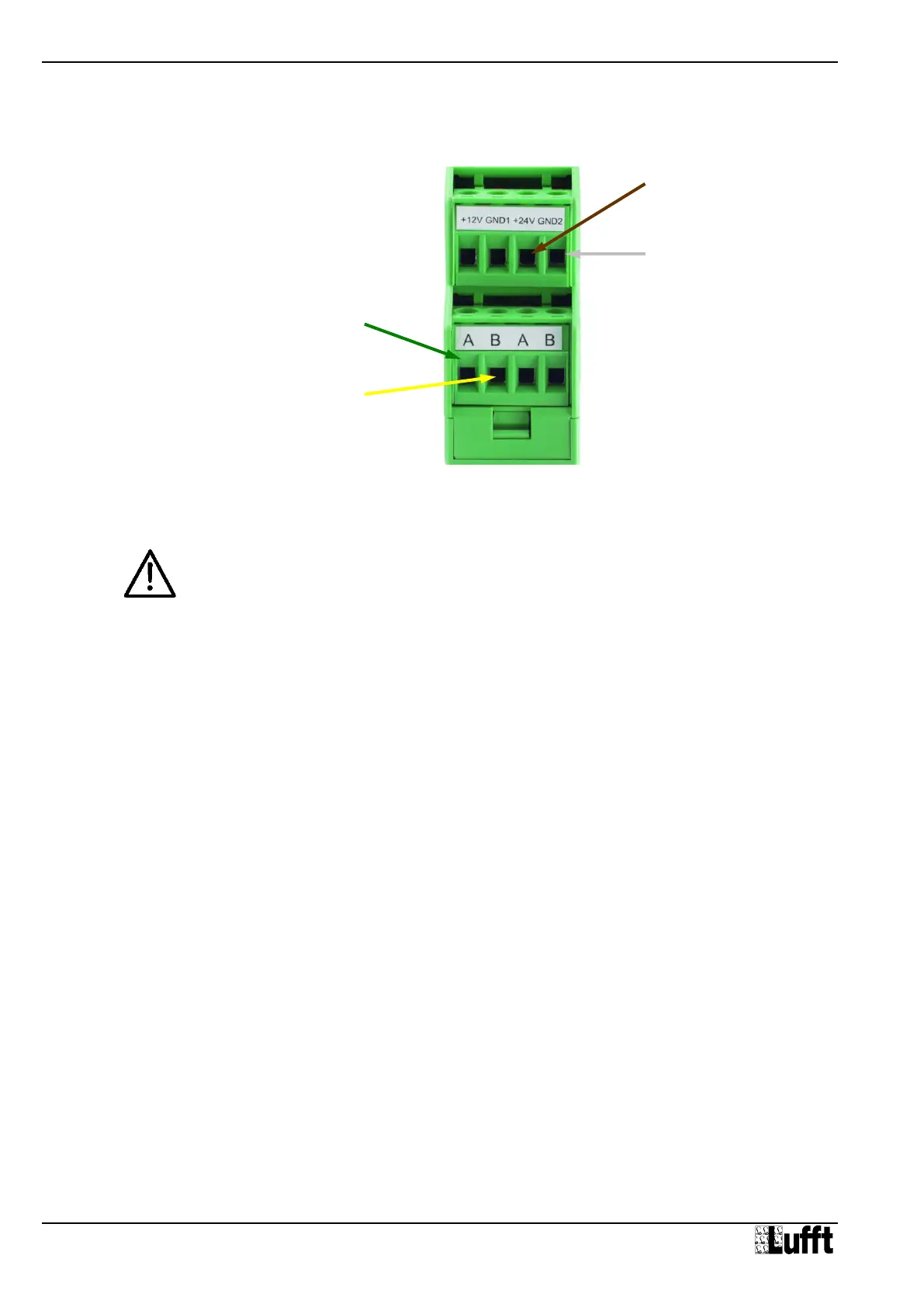
Figure 7: Connection to
ISOCON-UMB
8.3 Connection to ISOCON-UMB (8160.UISO)
Warning: The heating voltage (red = positive heating voltage; blue = heating voltage
ground) is not connected to the ISOCON-UMB but wired direct to the power supply unit.
During installation please also refer to the operating manual for the ISOCON-UMB.
8.4 Use of Surge Protection (8379.USP)
When using surge protection (Order No.: 8379.USP), please pay attention to the connection
example in the surge protection operating instructions.
8.5 Connection of the Leaf Wetness Sensor
The sensor versions WS401-UMB and WS601-UMB (precipitation measurement by rain
gauge) can be equipped with an optional external leaf wetness sensor.
The connection terminals for the leaf wetness sensor are located inside the rain gauge
module. The sensor connection cable is put through the cable bushing in the wall of the rain
gauge module and connected to the terminals (see Chap. 18.1).
Terminal assignment for Leaf Wetness Sensor WLW100:
1 blank (shield) Ground
2 red Signal Voltage
3 white Sensor Supply Voltage 5V
8.6 Connection of External Temperature and Precipitation Sensors
External sensors are to be connected to pins 5 and 6 of the plug connector, i.e. to the gray
and pink wires of the cable delivered with the Smart Weather Sensor.
The temperature sensors as well as the external rain gauge are unipolar, so any connection
sequence can be chosen.
The type of external sensor has to be set using the UMB Config Tool.
For details please refer to Chapter18.
Brown: Positive voltage supply
+24V
White: Supply voltage ground
GND2
Yellow: RS485
Interface B