Do you have a question about the Lull 944E-42 and is the answer not in the manual?
Provides general directions for accomplishing service and repair procedures, emphasizing safety and equipment reliability.
States that the manual is based on latest information and JLG reserves the right to make changes without notice.
Mandates understanding the Operation & Safety Manual before operating the machine and keeping it accessible.
Instructs to place 'Do Not Operate' tags on the ignition key switch and steering wheel before service.
Highlights the importance of reading and complying with all safety messages to avoid injury or death.
General safety statements for maintenance, including personal safety gear, lifting, and hand tool usage.
Details hazards related to engine, ventilation, soft surfaces, fluid temperatures and pressure, and tires.
Emphasizes checking that all safety decals are present and readable on the machine.
Stresses using only authorized JLG parts to maintain performance, durability, safety, and warranty coverage.
Provides torque values for various SAE fastener sizes and grades, with and without Loctite.
Details specifications such as travel speeds, hydraulic cylinder performance, electrical system, engine performance, and tires.
Lists capacities for engine oil, fuel, cooling system, hydraulic system, transmission, transfer case, and axles.
Outlines maintenance tasks required at 10, 50, 100, 250, 500, 1000, and 2000 hour intervals.
Provides lubrication schedules for the machine, specifically detailing 50-hour intervals.
Identifies and illustrates the components of the boom system for reference throughout the section.
Describes the operation of the three-section boom assembly, including extension, retraction, and lift functions.
Provides sequential instructions for removing and installing boom sections, emphasizing safety.
Details procedures for chain inspection, lubrication, tension checks, adjustments, and replacement.
Explains how to inspect, install, lubricate, and replace boom wear pads, including gap specifications.
Covers the removal and installation procedures for the quick attach assembly, including pin inspection.
Outlines daily and yearly inspection criteria for forks, including cracks, bends, and wear.
Provides a reference guide for common boom problems, their causes, and recommended remedies.
Details procedures for lowering the boom in case of engine power loss or hydraulic line failure.
Identifies major assemblies of the machine's cab and covers for operator/mechanic familiarity.
Covers cab safety, emphasizing that modifications can impair protection and require replacement if damaged.
Details removal and installation for steering column, steering valve, steer select valve, and brake valve/pedal.
Covers components specific to the enclosed cab, such as wipers, washers, and the heater/defroster system.
Provides instructions for safely removing the cab, emphasizing inspection of structural integrity.
Details the procedure for installing a new cab, including alignment, connections, and final checks.
Covers the removal and installation procedures for the valve plate assembly.
Identifies major assemblies of axles, drive shafts, wheels, and tires for operator/mechanic reference.
Provides important notes on drive shaft balancing, cleaning parts, and proper inspection of moving parts.
Covers axle serial number plates, specifications, internal service, maintenance, and replacement procedures.
Details inspection, maintenance, cleaning, drying, removal, and installation procedures for drive shafts.
Provides guidelines for selecting replacement tires and procedures for removing and installing wheel assemblies.
Covers brake disc inspection for wear and procedures for brake testing and maintenance.
Outlines the necessary steps for safely preparing and towing a disabled machine.
Illustrates and identifies major assemblies of the transmission for user understanding.
Explains the location and importance of the transmission serial number for correspondence.
Directs users to Section 2 for oil specifications and maintenance, and lists available service manuals.
Provides instructions for transmission removal and installation, emphasizing cleanliness and safety.
Offers a guide for diagnosing and resolving common transmission problems such as shifting issues and noise.
Identifies major assemblies of the transfer case for user understanding.
Describes the ZF Model TB92-I4 transfer case and provides information on serial numbers and maintenance.
Details procedures for transfer case removal and installation, stressing cleanliness and safety.
Provides a reference for common transfer case problems, including noise, leaks, and overheating.
Covers disclaimer, scope, component terminology, serial number, and general specifications for the engine.
Details radiator pressure cap function and procedures for radiator/oil cooler removal and installation.
Refers to Section 9.5 for descriptions of the engine electrical system, starter, alternator, and primary wiring.
Covers diesel fuel recommendations, fuel tank removal, disassembly, cleaning, and installation procedures.
Provides instructions for removing and installing the exhaust system components, emphasizing alignment and clearance.
Details the removal and installation procedures for the air cleaner assembly, including the intake hose.
Provides comprehensive steps for engine removal and installation, including disconnecting various systems.
Offers a chart for diagnosing engine problems based on fault codes, SPN codes, FMI codes, and Cummins descriptions.
Identifies and illustrates the location of hydraulic components for operator/mechanic reference.
Emphasizes hazards associated with hot hydraulic fluid, contamination, and proper procedures for disconnecting lines.
Details the use of pressure test kits and flowmeter kits for diagnosing hydraulic system issues.
Covers hydraulic circuit pressures, testing procedures, and includes a hydraulic schematic for the 944E.
Explains the function, draining, filling, replacement, cleaning, and inspection of the hydraulic oil reservoir.
Describes the pump's function, analyzes common failure causes, and provides removal/installation procedures.
Details service procedures for the valve plate assembly, main control valve, joysticks, and pilot select valves.
Covers cylinder disassembly, cleaning, inspection, assembly, installation, and torque specifications.
Identifies and illustrates the location of electrical components for operator/mechanic familiarity.
Directs users to Section 2 for electrical system specifications.
Emphasizes following safety precautions outlined in Section 1 before servicing the machine.
Details fuse and relay locations in the engine compartment and cab, and provides a chart of cab harness fuses/relays.
Provides a directory of electrical symbols and detailed schematics for the 944E machine.
Illustrates breakdowns of constant power, start & charge, and auxiliary hydraulic circuits.
Covers starter testing, circuit checks, removal, and installation procedures.
Details alternator removal and installation, and checks to perform if the charging warning indicator illuminates.
Provides procedures for windshield wiper motor removal, installation, disassembly, and testing.
Details the removal, disassembly, and installation of cab heater controls and fan.
Covers ignition key switch, hydraulic oil filter pressure switch, dual hydraulic oil temperature switch, and others.
Explains removal, disassembly, inspection, replacement, and installation of dash switches.
Lists engine fault codes, SPN codes, FMI codes, lamp color, SPN descriptions, and Cummins descriptions.
Identifies major assemblies of the Stabil-TRAK™ system for operator/mechanic familiarity.
Explains the patented rear axle lock system and its activation conditions under various operating modes.
Provides a troubleshooting chart and diagrams for electrical circuits in different Stabil-TRAK™ system modes.
Outlines instructions and procedures for testing the Stabil-TRAK™ system's functionality.
Describes hydraulic circuit operations for FREE PIVOT, SLOW PIVOT, and LOCKED modes with troubleshooting.
Identifies and illustrates the major assemblies of the transfer carriage for user understanding.
Describes the 'Place Ace' feature formed by the carriage and cylinder, and its operational benefits.
Covers maintenance tasks including wear pad checks, roller gap checks, and replacement procedures.
Provides a guide for common transfer carriage problems like drifting, jerky functions, noise, and pad wear.
| Maximum Lift Capacity | 4000 lbs |
|---|---|
| Maximum Lift Height | 42 ft |
| Fuel Type | Diesel |
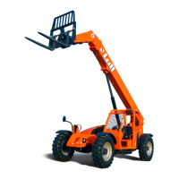
| Model | 944E-42 |
| Transmission | Powershift |