IMPAC pyrometers series IN 5 plus
15
Note:
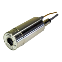
Please note that the optical profiles show nominal dimensions. The spot size di-
ameter or the focal distance may be slightly different due to lens tolerances.
Note:
The InfraWin program includes a Spot size calculator that roughly
estimates the unknown values. The values represented here are for reference pur-
poses.
Spot sizes for intermediate distances, that are not shown on the optical profiles, may be calculated using the
following formula:
D
D
M
a
a
M
+ − =
2
2
D
D
M
a
a
M
− + =
1
1
Ø M
Ø M
1
Ø M
2
a
a
2
Ø D
a
1
8 Instrument settings
Before using the pyrometer some basic settings should be taken. The basic settings can be done at the py-
rometer itself, some further settings can be done via interface and software InfraWin.
Settings at the instrument: The basic settings are emissivity, exposure time, analog output. These settings
can be adjusted at the pyrometer only in offline mode (see 8.2 Online- / offline mode (ONL/OFFL)).
Setting
s via serial interface: The pyrometer is equipped with a serial interface RS232 or RS485 (corre-
sponding to the ordered version) which can be used for connection to a PC. With the standard software In-
fraWin (or a self written communication software) the following settings can be done (the pyrometer must be
in online mode (ONL) to use this functions, see 8.2): emissivity, exposure time, analog o
utput, maximum
value storage, minimum value storage, reading of the instrument’s internal temperature, setting of an ad-
dress for bus control with RS485 interface, setting of the baud rate, function for compensating of the off-set
of the ambient temperature). Additionally InfraWin enables the temperature display and analysis.
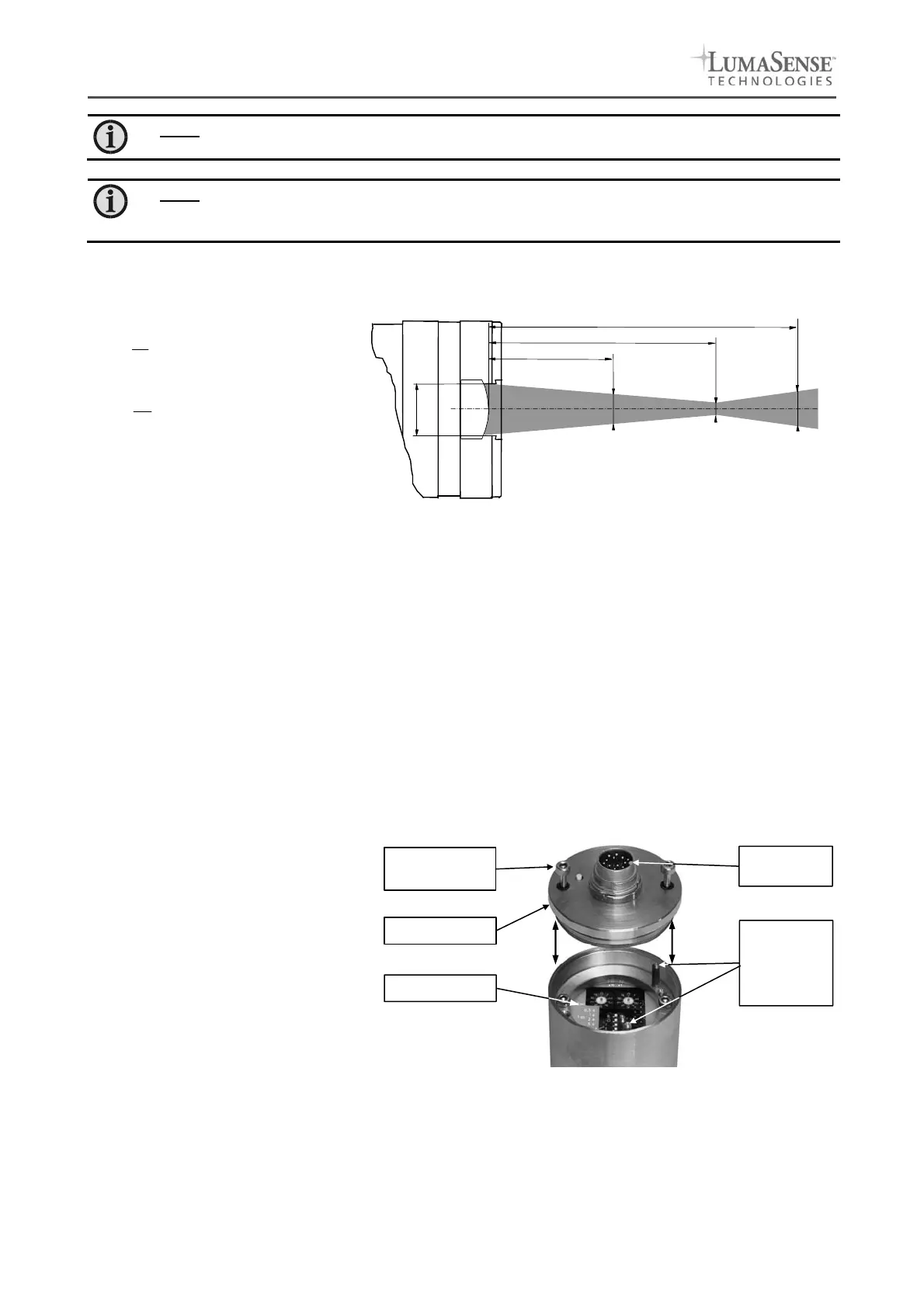
8.1 Switches at the instrument
The controls / switches are
located
under the rear cover of the pyrometer
and can be accessed by removing the
rear cover in the following way:
1. Disconnect the electrical
connection
2. Unscrew the rear screws with a
2.5 mm allen screw
3. Take the cover off, making sure it
remains straight (without bending
or twisting it).
Assembling:
When reassembling the cover, insert it carefully into the guide pins and then fasten it with the screws. The
connector cable can now be plugged in.
Rear cover
Switches
Locking screw
(allen key, 2.5 mm)
Aligning sup-
port (pin) for
correct mount-
ing of the rear
cover
Electrical
connection
 Loading...