13
3 Controls and Connections
3.1 Electrical Installation
The IGA 320/23 is powered by a voltage of 24 V DC (possible range 10 to 30 V, ripple < 0.5 V).
The instrument needs no warm up time and is ready for use immediately. For switching off the
instrument, interrupt the power supply or unplug the electrical connector.
To meet the electromagnetic requirements (EMV), a shielded connecting cable must be used.
The shield of the connecting cable has to be connected only on the pyrometer’s side. On side of
the power supply (switchboard), the shield must be open to avoid ground loops.
LumaSense offers connecting cables, but they are not part of standard scope of delivery. The
connecting cable has wires for power supply, interface, analog output; switch contact and
external clearing of the maximum value storage via contact and 8-pin connector (see Chapter 8
,
Reference numbers).
Warning: Follow common safety regulations for mains voltage (230 or 115 V AC) and
connecting additional devices operating with this mains voltage (e.g. transformers).
Touching mains voltage can be fatal. A non-expert connection and mounting can
cause serious health or material damages.
Only qualified specialists are allowed to connect such devices to the mains voltage.
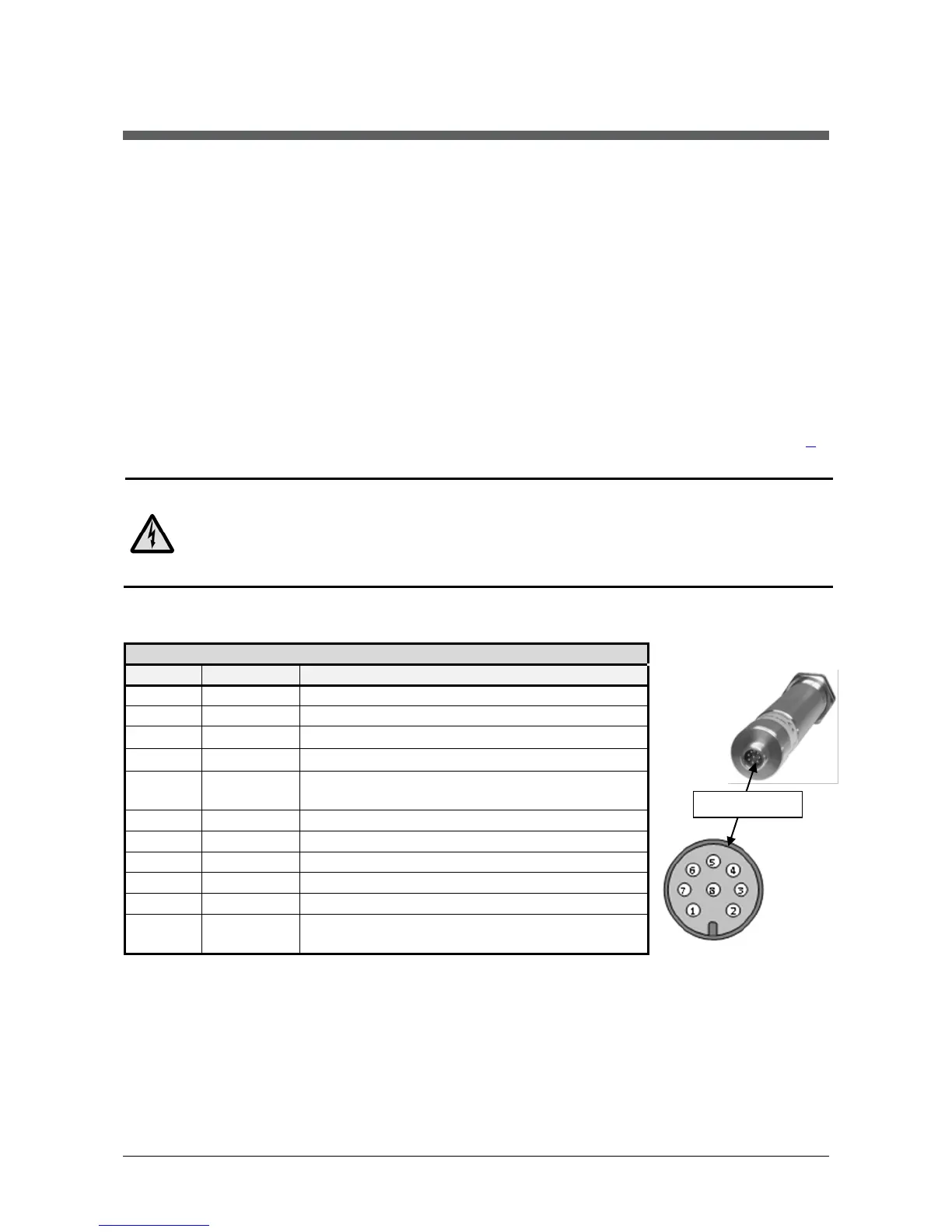
3.1.1 Pin assignment of the male socket on the back of the pyrometer

 Loading...