11
3 Controls and Installation
3.1 Electrical Installation
The instruments are supplied by 24 V DC (± 25%) and a ripple < 50 mV. Ensure correct polarity
when connecting the instrument to the power supply. The power consumption (in this case,
4 ... 20 mA) is also the measuring signal. The instrument doesn’t need any time for starting or
preheating and is immediately ready for operation. To switch off the instrument, interrupt the
instrument’s power supply.
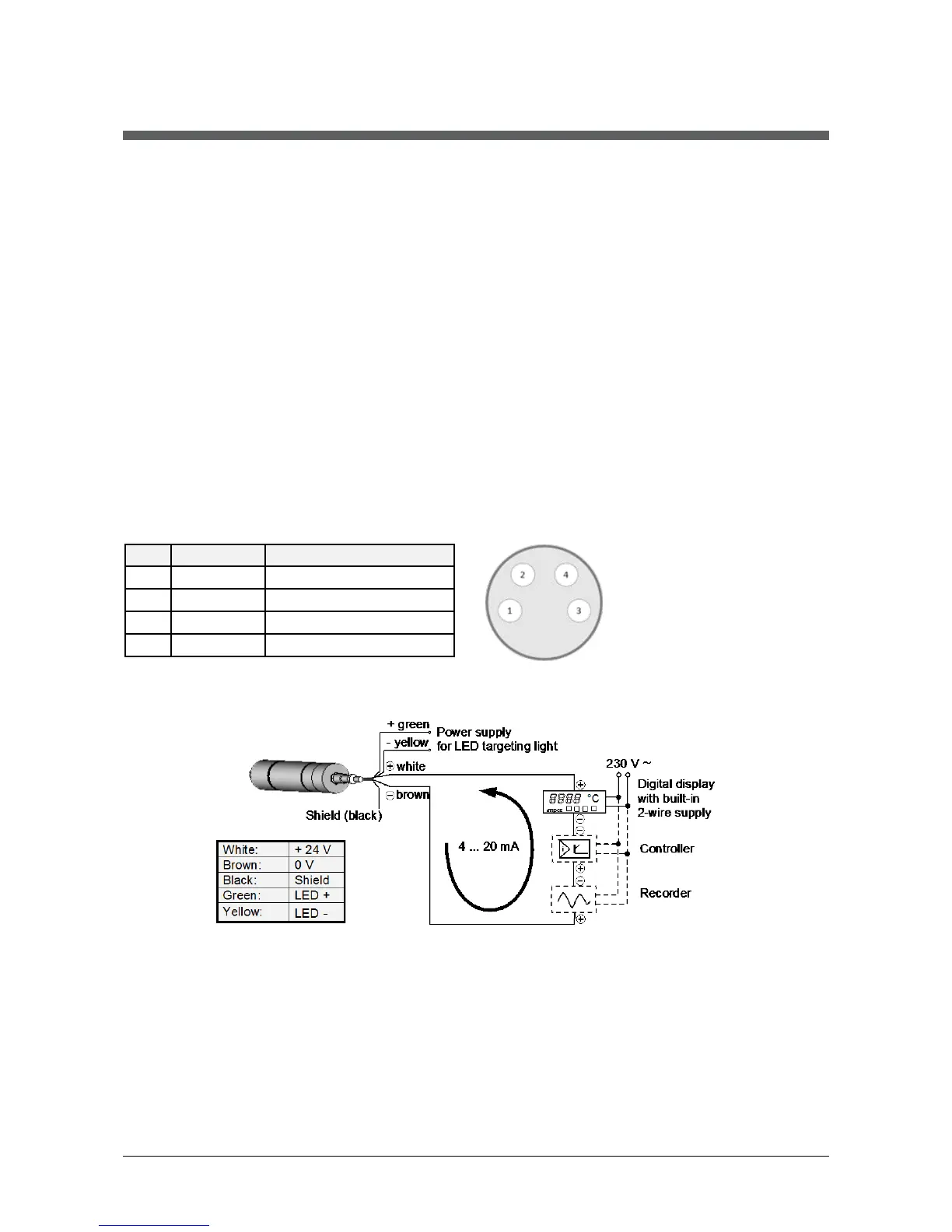
Cable colors: White: +24 V DC Green: LED +5 ... 30 V DC
Brown: 0 V Yellow: LED 0 V
Black: Screen
To meet the electromagnetic requirements, a shielded connecting cable must be used. The
shield of the connecting cable is usually only connected on the pyrometer side. If the connecting
cable is extended, the extension cable also needs to be shielded. Do not connect the shield in
the control cabinet to avoid ground loops.
3.1.1 Pin assignment of male socket on the back of the pyrometer
3.1.2 Connection of additional devices
Example for wiring using a digital display with integrated power supply: