8
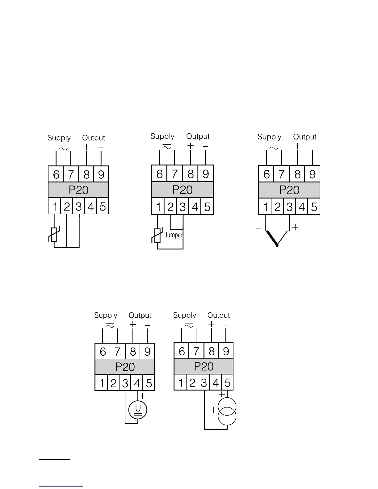
RTD in a three-wire
system
RTD in a two-wire
system or resistance
measurement
TC or voltage
- 60... 60 mV
0... 60 mV
- 150... 150 mV
0... 150 mV
Current
- 20... 20 mA
0... 20 mA
4... 20 mA
Voltage
- 10... 10 V
0... 10 V
0... 5 V
4.2. External electrical connection diagrams
The transducer has two sockets of terminal strips, which two plugs with
terminal screws are connected to. The way to connect external signals
is shown on the fig.1
The electrical connection diagram is also situated on the transducer
housing. In case of the transducer work in an environment with high
interferences, one must apply shielded wires in the transducer input.
Fig.2. Electrical connection diagrams of the P20 transducer.

 Loading...