Doc. No.: CP2 Control Panel_usermanual_D0077_EN_v1.7.docx7
4 MECHANICAL INSTALLATION
Please follow the recommendations below to maximize the potential of the system.
For detailed mechanical drawings, please see chapter 7.
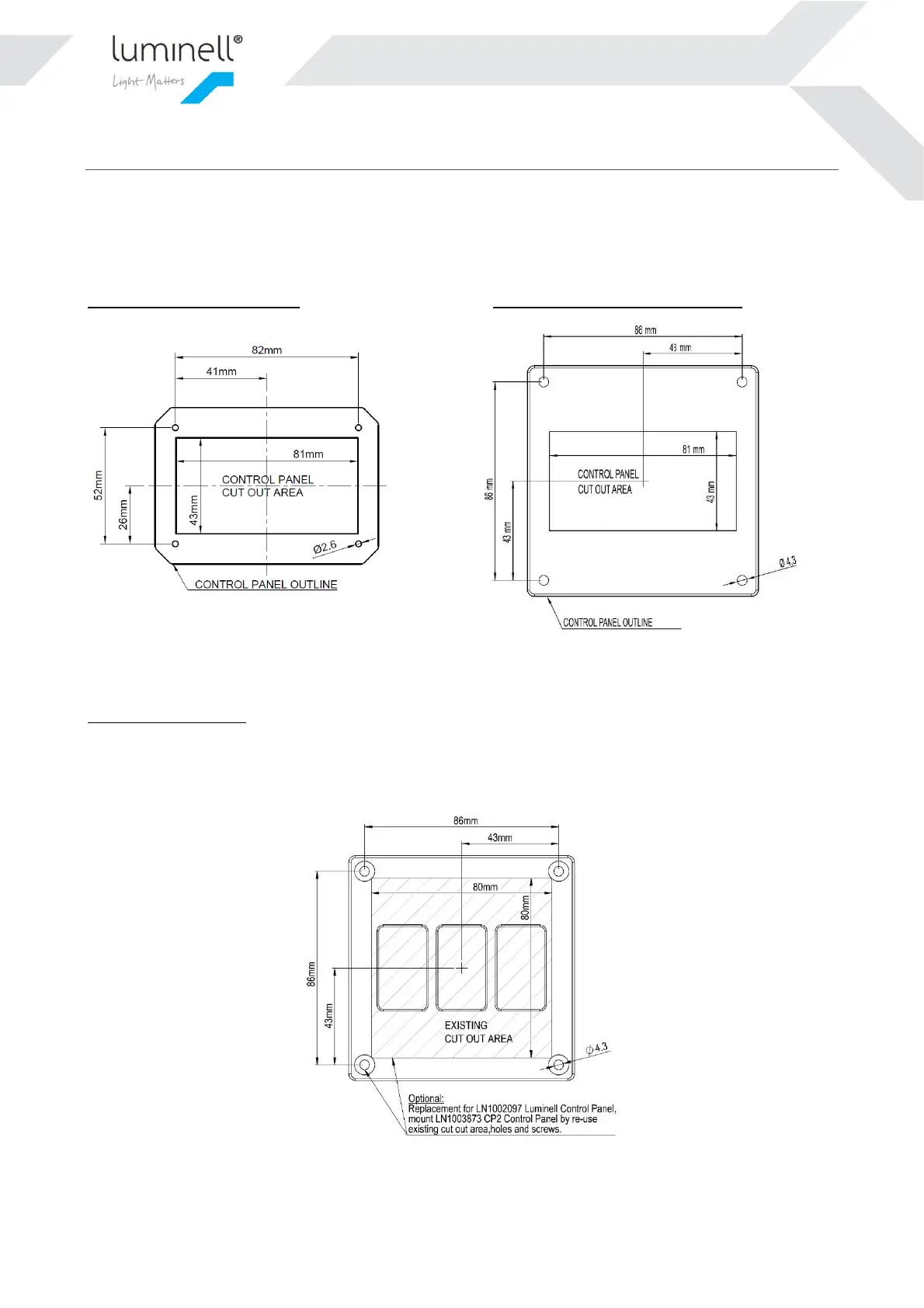
The Control Panel is designed to be flush mounted in a console top panel. Recommended console cutout is shown
below in figures. Secure the Control Panel with the four included screws using a T20 torx driver.
LN1003552 CP2 Control Panel: LN1003873 CP2 Control Panel Large:
Figure 2 and 3: Panel cutout (not actual size). The outermost line is the boundary of the physical product.
Optional refit solution:
CP2 Control Panel Large is a refit solution for the 1
st
generation Luminell Control Panel. It has the same outline
dimensions on the plate and will fit directly into the existing cutout. Please be aware that CP2 Control Panel needs
24VDC input.
Figure 2 CP2 Control Panal Large, re-usig the existing cutout area from 1
st
generation Luminell Control Panel.
 Loading...