Doc. No.: CP2 Control Panel_usermanual_D0077_EN_v1.7.docx7
5 ELECTRICAL INSTALLATION
This chapter describes how to do the electrical installation of the Control Panel
Risk of electric shock. Ensure that power is disconnected before carrying out any connections.
Remember – this is a 24VDC product! Connected voltage must not exceed 24VDC (+10%)!
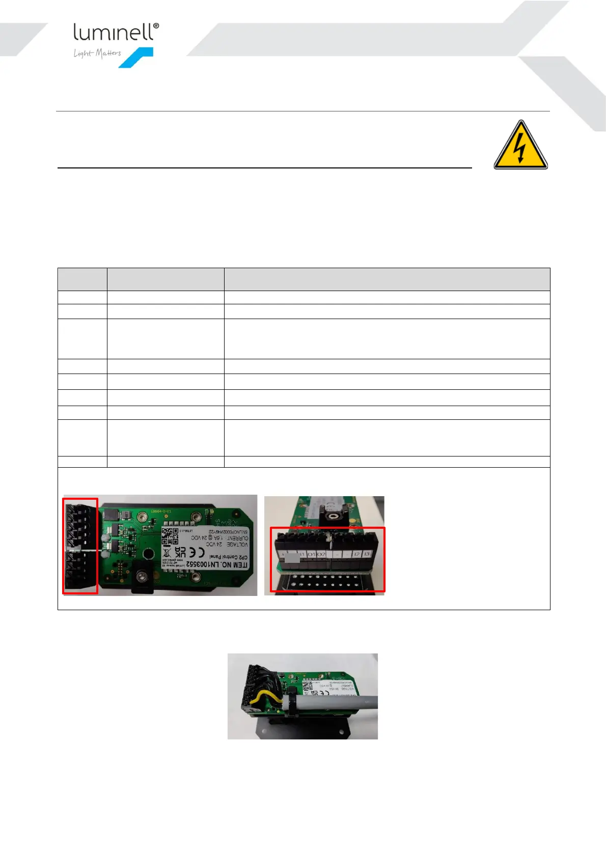
5.1 CABLE CONNECTION – CONTROL PANEL
Terminals supports up to 1,5mm
2
/16AWG wires. If larger cross sections are used, an external terminal lists in the
bridge console must be used. We recommend using shielded cables to avoid instability due to interference. The cable
shield shall be terminated on an external terminal list.
Use the supplied cable tie to securely attach the cable to the strain relief like indicated in Figure 3:
Figure 3 Securing the cable with a cable tie
NOTE: The cable used above is only for illustration – not included!
Common ground. Use for power minus
External input on/off
(Typically impulse
buttons and switches)
Light state toggle. Momentary/non-latching input. Toggle this input to
Ground with a potential free contact to switch between on/off state. On-
level intensity is the last setting from the Control Panel.
0-10V output for light intensity channel 1. Scales to 0-100% brightness
0-10V output for light intensity channel 2. Scales to 0-100% brightness
Common ground. Use for 0-10V signal or external inputs
Common ground. Use for 0-10V signal or external inputs
External input on/off
(Typically foot pedal or
latching switches)
Light state toggle. Latching input. Short this input to Ground with a
potential free contact to set ON state. Open contact to set OFF state. ON-
level intensity is the last setting from the Control Panel.
The terminal marking list above corresponds to the pictures below.
 Loading...