4
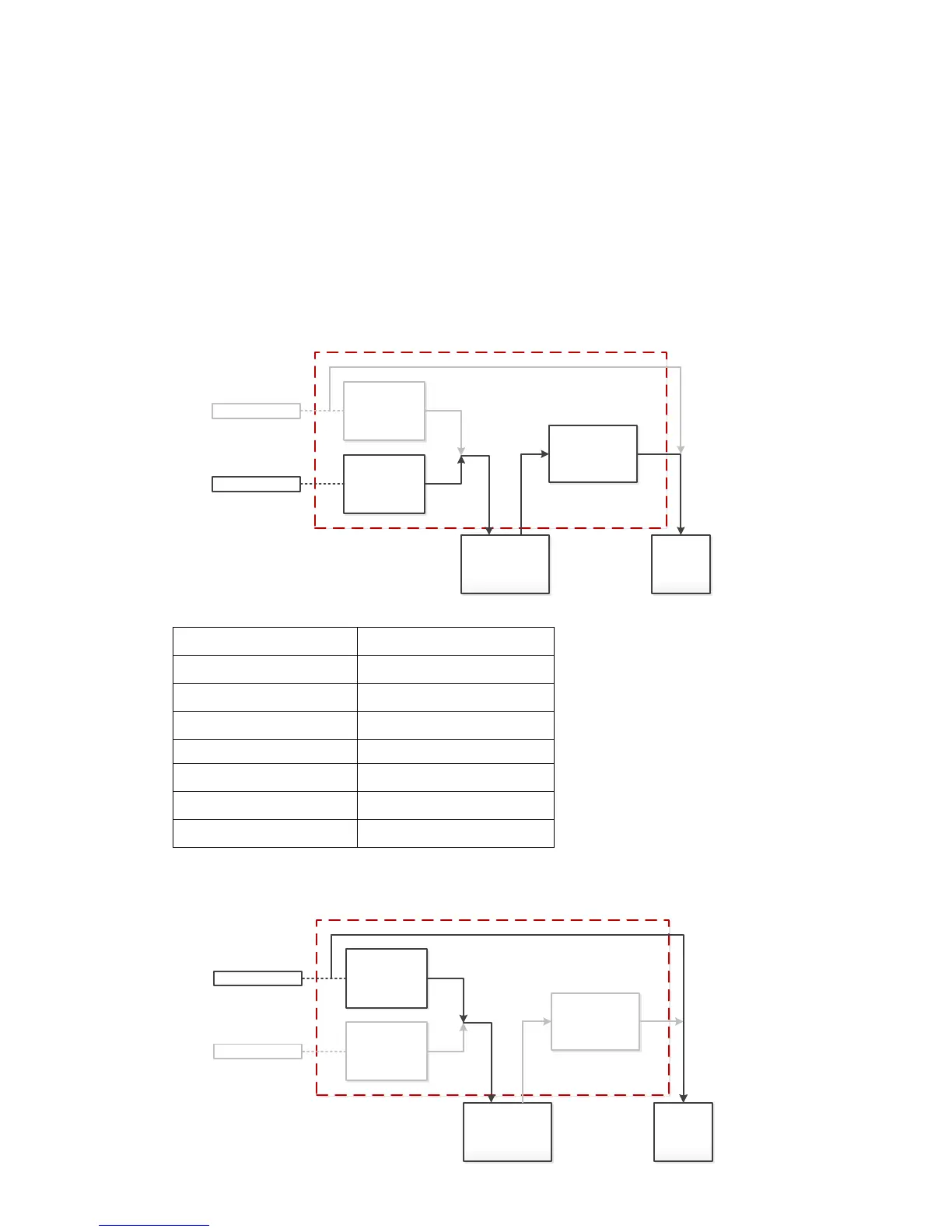
Operation Diagrams and Working Conditions
Abbreviation:
I
UC
, charging current from AC charger
I
SC
, charger current from solar charger
I
CHG
, total charging current of battery
I
DISC
, discharging current from battery
I
LOAD
, output current of AC load
sbu, output priority is solar >battery >utility
1) When utility source is not present, I
UC
=0, battery charged from solar source, I
CHG
=I
SC
, load powered from
solar and battery power, the Max. I
SC
goes up to 50Amp if solar panel with enough energy.
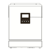
2) When solar source is not present, I
SC
=0, battery charged from utility source, I
CHG
=I
UC
, load powered from
utility, the Max. I
UC
limited at 20Amp for 1KVA, and 30Amp for 2KVA/3KVA.