32
• Faults on the machine or its guards, safety devices and blade
have to be reported to the person in charge as soon as they are
discovered.
• Use only the transport devices to move the machine. Never use
the guards for handling and moving the machine.
• While you are moving the machine it is best to cover the top part
of the blade, e.g. with the guard.
• Do not cut rebates or grooves without fitting a suitable guard,
e.g. a tunnel-type guard, over the saw table.
• Circular saws must not be used for slotting jobs (cutting grooves
which end in the workpiece).
• Inspect the microswitch of the sliding table regularly to ensure it
works correctly. You are allowed to operate the saw only when
the sliding table is correctly mounted.
Important:
Risk of injury! Never reach into the running saw blade.
Wear goggles
Wear ear-muffs
Wear a breathing mask
Noise emission values
Idle mode
Sound pressure level LPA 93,5 dB(A) 82,1 dB(A)
Sound power level LWA 108,8 dB(A) 96,8 dB(A)
The quoted values are emission values and not necessarily reliab-
le workplace values. Although there is a correlation between emis-
sion and immission levels it is impossible to draw any certain con-
clusions as to the need for additional precautions. Factors with a
potential influence on the actual immission level at the workplace
include the duration of impact, the type of room, and other sources
of noise etc., e.g. the number of machines and other neighboring
operations. Reliable workplace values may also vary from country
to country. With this information the user should at least be able to
make a better assessment of the dangers and risks involved.
5. TECHNICAL DATA
Artnr. ..............................................20843 -0108 -0207
Luna........................................................... BCS 315
AC motor................................................V 230 1-fas 400 3-fas
................................................................... ~ 50Hz
Power P..................................................W 2200
Idle speed n
0
......................................min-
1
2800/4300
Cutting-off wheel................................mm Ø315xØ30x3,6
Number of teeth......................................... 24
Main table size....................................mm 800 x 350
Sliding table dimensions.....................mm 1000 x 300
Sliding length max..............................mm 580
Cutting height max..............................mm 73/0°-49/45°
Height adjustment infinite.................. mm 0 -73
Tilting saw blade infinite .............0° - 45°
Extractor socket...............................Ø mm 100
6. BEFORE PUTTING THE MACHINE
INTO OPERATION
• Unpack the bench-type circular saw and check it for damage
which may have occurred in transit.
• The machine has to be set up where it can stand firmly, e.g. on a
work bench, or it must be bolted to a strong base. The machine
must stand securely, i.e. the saw must be securely bolted to the
floor.
• All covers and safety devices have to be properly fitted before
the machine is switched on.
• It must be possible for the saw blade to run freely.
• When working with wood that has been processed before, watch
out for foreign bodies such as nails or screws etc.
• Before you actuate the On/Off switch, make sure that the saw
blade is correctly fitted and that the machine’s moving parts run
smoothly.
• Before you connect the machine to the power supply, make sure
the data on the rating plate is the same as that for your mains.
7. ASSEMBLY
Important! Pull out the power plug before carrying out any
maintenance, resetting or assembly work on the cutting-off
machine!
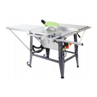
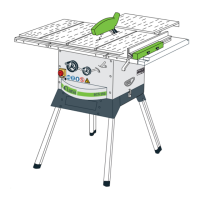
7.1. Setting up the saw (Fig. 1-9)
• Place the saw with the table facing down on a flat surface.
• Fasten the four legs (18) to the machine body on the inside,
using four screws (SW13) for each leg. When you insert the legs
make sure that the lugs of the legs fit the shape of the mounts
provided.
• Mount the four rubber feet (25) on the legs.
• Fasten the chassis (15) to the legs on the inside, using two scre-
ws for each leg. In doing so, the 4 spacers (26) must be inserted
between the legs and the angle bracket (22) of the chassis. When
assembling, make sure that the rounded side of the angle brack-
et faces the bottom of the machine.
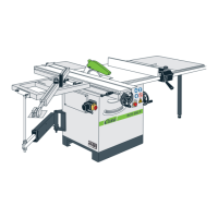
• Turn the saw upside down and place it on the floor.
• Carefully insert the sliding table (3) in the slideways (24) and
push to the point where the locking hook (10) latches home.
• Screw the mount for the extractor hose (29) and the tool hook
(28) to the machine body (see Fig. 6 and 7).
7.2 Using the chassis (Fig. 11)
• To swing the chassis out, gently lift the saw at the back (a) and
push the wheels backwards (15) (b).
• Then lower the saw again, keeping it in this same position.
• The saw is now standing on the wheels and be transported by
one person with the aid of the handles (16).
Important: Never lift the saw by the sliding table.
• Important: After transportation, the chassis (15) must immedi-
ately be retracted in order to ensure the saw is standing secure-
ly.
• To do this, return the wheels to their starting position by fol-
lowing the sequence in reverse.
7.3 Fitting / removing the saw blade guard (Fig. 9)
• Mount the saw blade guard (2) on the splitter (5) so that the
screw fits through the hole (45) in the splitter.
• Do not tighten the screw (37) too far – the blade guard must be
able to move freely.
• Fasten the extractor hose (14) to the extractor adapter (16) and
to the extractor socket of the blade guard (2).
• A suitable extractor system has to be connected to the outlet of
the extractor adapter (14).
• To remove the saw blade guard, proceed in reverse order.
Important!
The guard hood (2) must always be lowered over the work-
piece before you begin to cut.
 Loading...