20
Please check the delivery for completeness and mint condition!
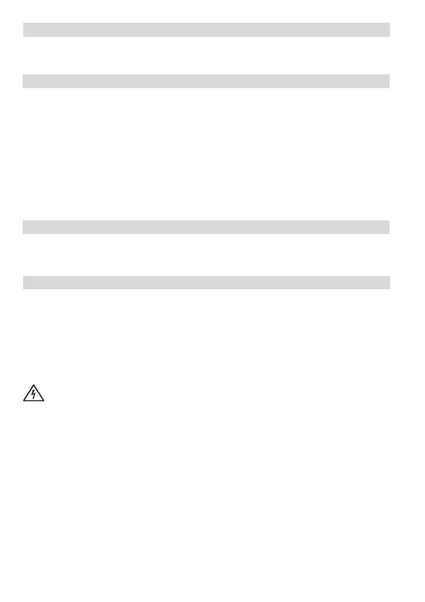
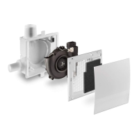
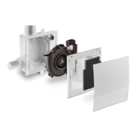
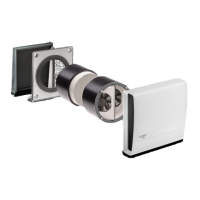
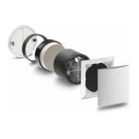
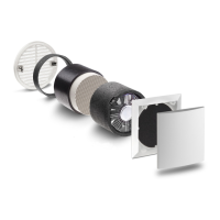
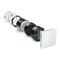
2 Shipping Unit
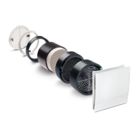
Clamp-in fan unit Silvento KL-EC included:
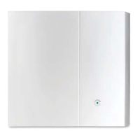
Grill frame with filter and decor screen
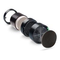
Fan unit with nozzle DN80
Seal (A) (Stick on when replacing Skalar-V)
Snap-in element (B), Mains connection terminal (C)
Installation Manual and Screw accessories
Product data sheet and energy label
The control board (D) is not part of the shipping unit and must be ordered separately.
3 Installation Examples
For fire protection, the shaft wall must have the required fire resitance duration!
If necessary, correct the position of the non-return valve. For possible alignment see 1 Notes.
5 Installation - Installation in a wall cutout
5.1 Connect flextube (DN 80 or DN 75, approx. 50 to 100 cm long) to the main line. Fasten the
sliding connection pipe (F) to the flextube. Seal connections with sealing tape or clamps.
5.2 Make a wall cutout according to the specified dimensions. Installing the pre-wall cladding.
Fix the flextube and power cable ready to hand in the wall opening.
5.3 Remove snap-in element (B) with the mains connection terminal (C) from the fan and attach
the mains connection terminal to the mains cable according to the selected connection dia-
gram (see 6 Electrical connection).
Attention! Disconnect the mains cable from the power supply!
5.4 Plug on and snap in the snap-in element with the mains connection terminal and
connected mains cable.
Attention! The mechanical installation of the power cable must also be voltage-
free! Alternatively, use a flexible cable if necessary!
5.5 Snap-in element with mains connection terminal in place!
5.6 Push the sliding connection pipe in until it reaches the stop (if necessary, correct the position
and fit of the non-return valve, see figure 5.9)! Slide the fan unit into the wall cutout.
5.7 Position and correction of the non-return valve (important for ceiling installation):
In the installation position, the non-return valve in the exhaust vent must close by its own
weight. The non-return valve can be pulled out inwards for correction.
Pay attention to a correct position according to the drawing.
1 Notes
- Installation in area 1 in bath and shower rooms in accordance with VDE 100 is permissible
- Fan installation for use as extractor hood not permitted