Application Note #489
10 www.lutron.com
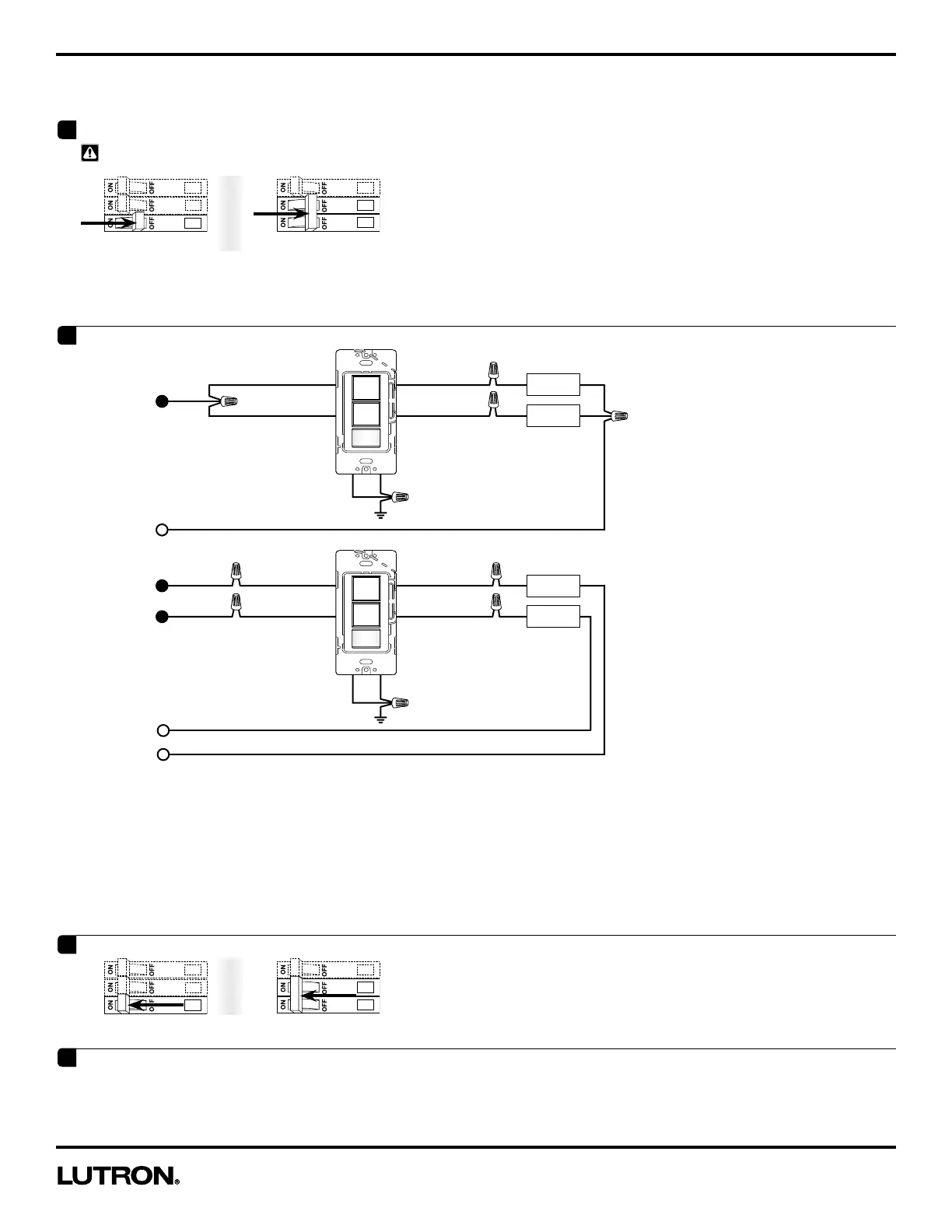
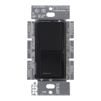
Wiring Diagrams
NOTES:
• Leave wallplate off if custom settings are desired.
• The Dual-Circuit Occupancy Sensing Switch was designed for wiring flexibility. When wiring Circuit 1, you may use either black wire to connect
to the line or load side. When wiring Circuit 2, you may use either black-orange wire to connect to the line or load side.
• Please note that both black wires correspond to Circuit 1, and both black-orange wires correspond to Circuit 2.
• If replacing existing switches with this product, it is recommended that you label the wires AFTER turning power OFF (Step 1), but BEFORE
removing the previously installed switches and proceeding with wiring the Dual-Circuit Occupancy Sensing Switch
a
Device will not function if Black wires (Circuit 1/ Line 1) are not wired.
b
Device will not function if it is not grounded.
Black
a
GreenBare
Black-Orange
Neutral
Load 1
Load 2
120-277 V~
Black
Black-Orange
Ground
b
A
. Single-Line Wiring
B
. Two-Line Wiring
Black
a
Green
Ground
b
Bare
Black-Orange
Neutral 2
Line 1
Load 1
Load 2
Line 2
120-277 V~
Neutral 1
Black
Black-Orange
120-277 V~
2
Connect dual-circuit Sensing Switch
WARNING! Shock Hazard. May result in serious injury or death. Turn power OFF at circuit breaker(s) before installing the unit.
1
Turn power OFF
A
.
Single-Line
B
.
Two-Line*
* Wiring must comply with 2011 NEC code 210.7 for wiring Multiple Branch Circuits: Where two or more branch circuits supply devices or
equipment on the same yoke, a means to simultaneously disconnect the ungrounded conductors supplying those devices shall be provided at the
point at which the branch circuits originate.
OR
3
Turn Power ON
OR
A
.
B
.
4
Wait for 2 minutes
NOTE:
After restoring power to the unit, when wiring is complete, the unit will not manually control the load for the first 30 seconds after power-up.
The unit will also not operate the sensor until 2 minutes after power-up.