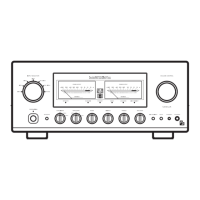
SCHALTER UND BEDIENUNGSELEMENTE
22. PHONO Jacks
Output of a magnetic
cartridge
(|'"4M,
Ml, MC
type)
can be
reproduced
through these
jacks.
With the cartridge
selector
placed
in
the
MC
position
input sensitivity
is 300pV,
and w;th the
MM
position
the
sensitivity
is 2mV. lnput
impedance
is 50k ohms.
23. CD Jacks
(180mVl
Output
from compact disc
player
can
be
reproduced
through these
jacks.
24. TUNER Jack
(180mV)
This terminal
is
for
playback
of a tuner
(AM/FM/LW/SW).
lnput
sensitivity
is 180mV and input impedance
is 40k ohms.
25. TAPE-I REC OUT Jacks
A siqnal
for
recording
is taken
from
these
jacks
(always
available when
an input signal
is
given
to any of the input
terminal).
ln case
the
Dubblng
Button
is
depressed, the
recording signals come
from
the TAPE-2
jacks.
26.
TAPE-I MONI
iacks
(180mV)
Playback
of the line output
of a
tape
recorder is
posslble
from
these
jacks.
lt is
put
into
operation when the Tape
Selector Switch is
in
the
"protruded" position
and the
Monitor Button
is
depressed. In case a 3-head tape recorder
is
used, simultaneous
playback
monitoring
is
possible.
lnput
sensitivity
is
1B0mV. lnput impedance is
40k
ohms.
27
. T APE-2
R EC
OUT Jacks
These
lacks
offer the same
function
as that of the TAPE-1
R EC.
OUT
jacks.
28. TAPE-? MONI
Jacks
(180mV)
These
jacks
offer the same
function
as that of the TAPE-1
MON
I
jacks.
lt
is
put
into operation when
the Tape Selector
Button
and the
Monitor
Button are depressed.
29.
30. Speaker
Terminals
{A
and B}
The speaker
systems
should be
connected
to these ter-
minals. Turn the
cap
cf the terminal counter-clockwise
and
clamp the
bare
speaker
cord
on it, then
fasten
the cap tiqht.
The red terminal
is for
(+)
and the black
for
(-).
For further
details,
refer to Connection of
Speakers.
Note: When
you
are to
use
these
two terminals at the
same
time, be careful that
the
impedance
of each
speaker
system should
exceed
I ohms.
31. AC
Power
Cord
Connect
the AC
plug
at the end
of this cord to
the
type of AC
outlet in
your
listening
room.
1. Netzschalter
Durch Drücken dieser Taste wird
das Gerät
eingeschaltet;
Die
Kontroll-Lampe
leuchtet auf.
Eine verzögernde
Muting-
schaltung
läßt den Verstärker binnen 3 Sekunden
betriebs-
bereit
werden.
Erneutes
Drücken der Taste schaltet das Gerät
aus.
2, Kopfhörerbuchse
Das Anschließen eines stereophonen Kopfhörers ermö-
glicht
lhnen
einen ungestörten
Musikgenuß. Das Ausgangs-
signal
ist immer
vorhanden, unbeachtet
der
Position
der
Lautsprecherwah
lschalter.
Um ungestört hören zu
können,
achten
Sie
jedoch
darauf,
daß beide Lautsprecherwahlschalter sich in
der
ungedrückten
Position befinden.
3. Lautsprecherwahlschalter
Dieser Verstärker ermöglicht lhnen
den Anschluß von 2
Lautsprecherpaaren, A und B. Sie können mit Hilfe
der
beiden Schalter
zwischen
unabhängigem und
gleichzeitigem
Betrieb der beiden
Lautsprecherpaare
wählen, ln der unge-
drückten
Position
sind die Lautsprecher nicht
mit dem
Verstärker
verbunden und
Sie können lhre Musik
per
Kopf-
hörer hören.
Denken Sie bitte daran,
daß die
lmpedanz 4
ohm
nicht unterschritten wird,
wenn
Sie
zwei
Lautsprecher-
paare
gleichzeitig
laufen lassen, da diese
beiden Ausgänge
parallel
geschaltet
sind. lm Falle
des
Anschlusses von zwei
Lautsprecherboxen-Paaren
gleichzeitig
darf somit
jede
Box
nicht unter
8
ohm lmpedanz haben.
4. Einschalter für Klangregelung
lst
dieser Schalter
gedrückt,
is1 die Klangregelung einge-
schaltet. Die Bedienungselemente
(16),
{17)
sind dann
betriebsbereit.
ln
der ungedrückten Position
ist die Klang-
regelschaltung vollständig
überbrückt
und
damit außer
Funktion; ein linearer Frequenzgang ist
in dieser Schalter-
positi
on
gewährleistet.
5. Subsonic-Filter
Wird
dieser Schalter
gedrückt,
werden Geräusche unterhalb
von 20 Hz mit einer Steilheit von
6 dB/Okt.
reduziert.
Dieser
Filter
dient der Unterdrückung von
Störsignalen im
lnfraschallbereich, hervorgerufen
durch
Plattenspielermotor-
rumpeln oder
verwellte
Schallplatten.
 Loading...