P a g e | 8
After assembling the mounting brackets, they can now be installed in the pre-selected location. Please again refer to
the mounting bracket spacing diagram, page 4. The spacing of the outer-most sets of holes of the mounting brackets is
48”. The spacing of the inner-most sets of holes is 45-1/2”. These numbers are given to you as a reference for planning.
Mount one single mounting bracket first. Choose the side which may be the closest to a combustible material. This way,
it is easier to measure and determine that the exact minimim clearance is being adhered to . If mounting onto wood,
predrill pilot holes using ¼” drill. (If surface is other than wood, then anchors will need to used- follow instructions that
come with the anchors) If the mounting bracket is resting entirely on the wood surface, mount using all (4) screws per
bracket. It mounting on the edge of a wood joist, then use the 2 holes closest to the vertical wall of the bracket.
Install the second bracket such that the outer most sets of holes are 48” from outer-most set of holes on the first
bracket. THIS WILL CREATE A RESULTING DIMENSION OF EXACTLY 49-3/32” BETWEEN THE EXTENSION ARMS OF THE
BRACKET. If not, then remeasure and mark again. Pre-drill and mount the second bracket.
Place the heater into location, on the ground , directly under the mounting brackets- Using 2 people, and 2 ladders,
carefully lift the heater into position. Place the heater inside the extension arms of the brackets and secure the heater
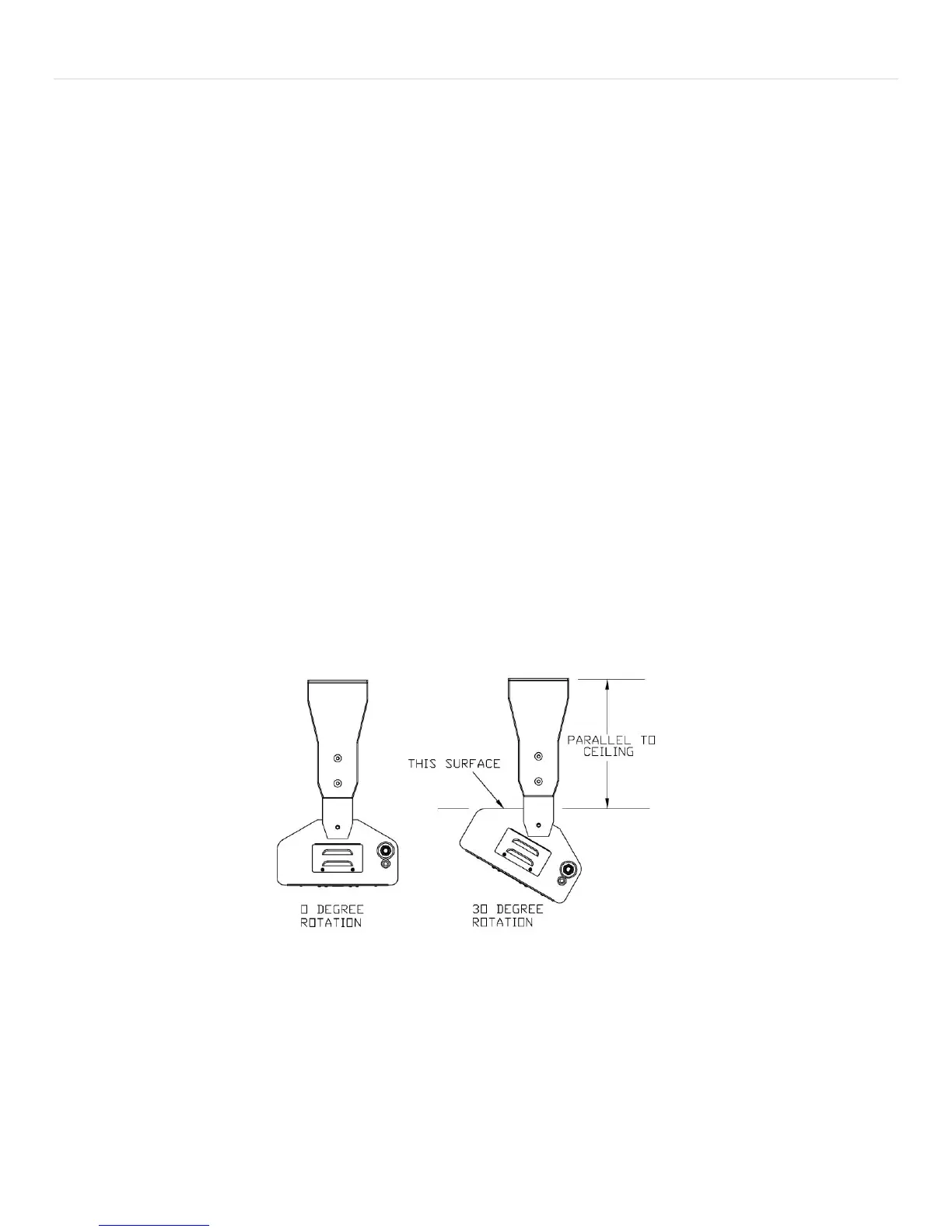
at both ends, first with (2) ¼-20 x 1” hex head bolts. Mount screws in the UPPER holes first. Tilt the heater into the pre-
determined angular position (0-30 degrees). Install the second set of ¼-20 x 1” hex head bolts through the curved slots
directly below the first holes. The maximum 30 degree angle will be achieved when the screw is ‘bottomed out’ at one
end of the curved slot. This angle can also be sited by looking at the angled surface on the back of the heater. When the
angled surface is PARALLEL to the ground (or the ceiling) the then heater is at 30 degrees. DO NOT MOUNT THE HEATER
MORE THAN 30 DEGREES, as damage can occur to the protective grill. Always use the 2 bolts per side and always use
the bottom curved slot for angle positioning (EXCEPTION- eave fascia mounting does not require bottom bolt for
mounting).
MAKING THE GAS CONNECTIONS
Gas connections will vary considerably depending on heater mounting location selected and the gas type (NG or LP)
being used. See also previous section ‘Gas Supply and Connections’. Prior to mounting the heater, the gas connections
were considered and an overall routing ‘plan’ was established. A minimum pipe size of ½” is required for inlet piping.
The supplied exit coupling of this heater is ½”FIP (female). A ½” leaver- handled manual gas shut-off valve should be
installed within 6 feet of the appliance to allow emergency gas shut-off and provide isolation for servicing.
 Loading...