www.lynxspring.com
®
WIRING INSTALLATION GUIDE
Lee’s Summit, MO 64086
sales@lynxspring.com
All Rights Reserved
Revised 1/10/2019
JENE-EG534-N4-V1
Page 3 of 5
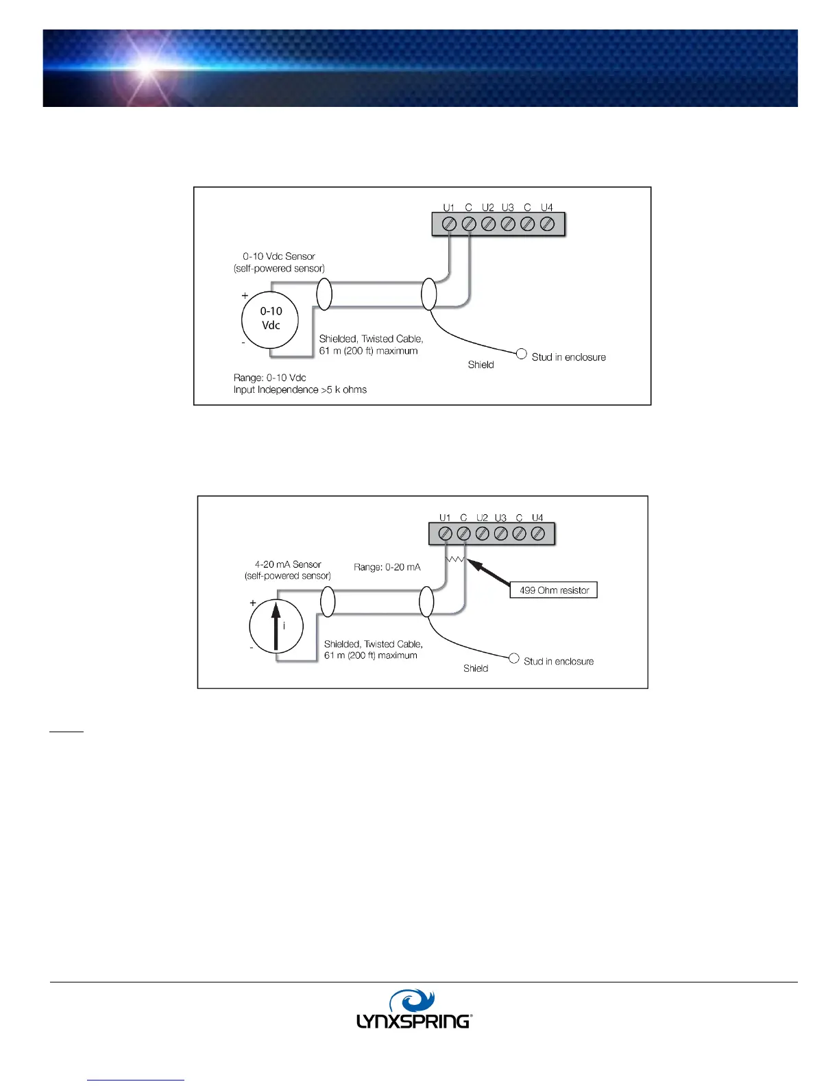
0-10 Vdc
The inputs support self-powered 0–10 Vdc sensors. Input impedance is greater than 5 k ohms. 0–10 volt accuracy is ± 2% of
span, without user calibration.
Figure 3 shows the wiring diagram. 0–10 Vdc sensors require a VoltageInputPoint.
4-20 mA
The inputs support self-powered 4–20 mA sensors. Input accuracy is ± 2% of span, without user calibration. Figure 4 shows
the wiring diagram, which requires a 499 ohm resistor wired across the input terminals. 4–20 mA sensors also require the
CurrentInputPoint.
Binary Input
Pulse
Pulse contacts may have a change-of-state (COS) frequency of up to 500 Hz with a 50% duty cycle.
Note: Minimum dwell time must be > 2 ms. For a pulse contact, use the CounterInputPoint in the station database.
Outputs
There are ten (10) N.O. digital relay outputs and eight (8) 0–10 volt analog outputs.
Relay Outputs
Each relay output is rated at 24 Vac or Vdc at 0.5 A.
Use a
BooleanOutputWritable in the station for each output. Figure 5 (page 4) shows an example wiring diagram.
Note: The 15-position DO connector has common terminals marked “C” that are isolated from each other. This is useful if
controlled loads are powered from different circuits.
 Loading...