www.lynxspring.com
®
WIRING INSTALLATION GUIDE
Lee’s Summit, MO 64086
sales@lynxspring.com
All Rights Reserved
Revised 1/10/2019
JENE-EG534-N4-V1
Page 5 of 5
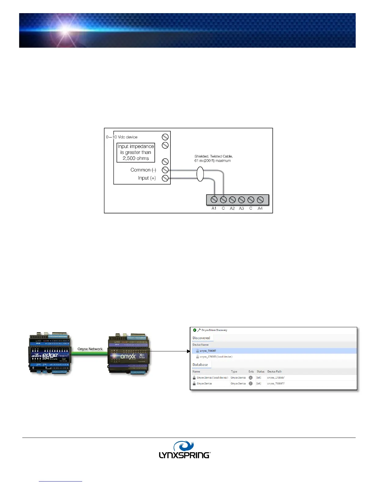
Analog Outputs
Analog outputs (AO) are referenced by the terminals labeled “A(n)” and “C” (ground). Each AO can supply a maximum of 20
mA over the entire 0 to 10 Vdc range. The minimum input impedance of a device controlled by an AO must be greater than
2,500 ohms. Typical wiring for an AO is shown in
Figure 7.
For each AO, use a VoltageOutputWritable in the station database.
Onyxx
®
IO (Software) Representation
In the Niagara 4 station interface, the JENEsys Edge 534 – N4 appears as one Onyxx IO Device, where the “DevicePath”
property is appended with a six-digit number. See
Figure 8. Upon discovery, if the JENEsys Edge 534 – N4 has 1-7 Onyxx XM
34IOs daisy-chained, the devices will show up as onyxx_######. The device number will match the number listed on the
device itself, unless different devices were programmed in the station previously. Refer to the physical devices to verify the
device ID number and match it to the discovered device. They may not appear in the wired order so verification must be
completed for proper device and point allocation to the physical Onyxx device. See
Figure 8. Each type of input or output
used requires a special Lynxspring Input/Output (Onyxx IO) point to be added in the station database. These components act
as the station interface to the physical I/O points. The Onyxx IO points you need for each input or output type are noted in
previous wiring sections in boldface.
Note: Add to a JENE-EG534-N4, up to 8
additional extender modules (at 34 points of IO
each) for a maximum of 306 points.
 Loading...