I E’ possibile installare ePower in configurazione multipompa
(solo modello ADVANCED) composta da un inverter Master
che pilota fino ad un massimo di 7 inverter Slave. L’inverter
Master determina il funzionamento degli inverter Slave.
Per abilitare la modalità multipumpa occorre:
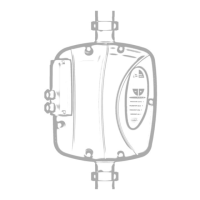
- Togliere il coperchio ed aprire uno dei fori posizionati nella
zona di preforatura. Applicare un pressacavo di dimensioni
adeguate al tipo di cavo utilizzato per il collegamento tra le
varie unità ed effettuare il collegamento utilizzando la
morsettiera J20 come in ”Esempio di collegamento in
modalità Multipompa”
- Impostare dal menu esteso il parametro 28 “Prossimo
OpMode” con il valore “MP”: Multipompa.
- Impostare dal menu esteso il parametro 4 “Config. Rete
ID” con un numero compreso tra 0 e 7. L’inverter con il
valore numerico piu’ basso rappresenta il Master del
gruppo.
- Impostare il parametro 47 “Potenza Nominale“ con il valore
di potenza nominale della pompa (P1).
(vedi parametro 47 nella sezione Menù Esteso). Nel caso
in cui sulla targa della pompa venga riportato solamente la
potenza utile P2, inserire come potenza nominale il valore
dato da P2/0.7. Per entrambi i valori di potenza (P1 e P2)
l’unità di misura è espressa in Watt.
- Dopo essere usciti dal menu esteso il display visualizza
per l’unità Master “MA” mentre per le unità Slave
visualizza “Ux” (dove x è il numero attribuito all’inverter con
il parametro 4).
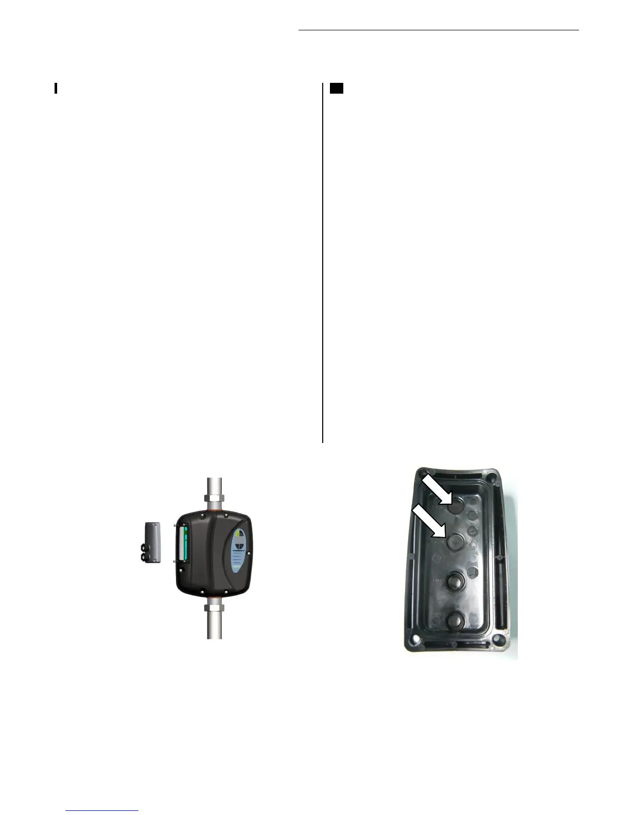
Esempio di collegamento in modalità Multipompa:
EN It’s possible to connect ePower in multipumps
configuration (ADVANCED model only) composed from
an inverter Master that can drive 7 inverter Slave.
To enable mutipump mode is needed:
- Remove the lid and open one of the holes located in
the area of pre-drilling. Apply a cable gland of
adequate size for the type of cable used for the
connection between Master and Slave and connect
them using the terminals J20 see “Connection
between Master/Slave”.
- Set the parameter 28 “Next OpMpde” with the value
“MP”: Multipump.
- Set the parameter 4 “Net Config ID” with a number
between 0 and 7. The inverter with lowest numerical
value is the Master of the group.
- Set the parameter N. 47 “Motor Power” with the
nominal power value of the pump (P1). (See
parameter 47 in Extended Menu section). If in the
pump is shown only the useful power P2, the
nominal power is given by P2/0.7. For both the
power values (P1 and P2), the unit of measurement
is expressed in watts.
- After exiting from extended menu, the Master unit
displays "MA", while the Slave unit displays "Ux"
(where x is the number assigned to the inverter with
parameter 4).
Connection between Master/Slave: