2016
5. Specification of parameters for control system
-13-
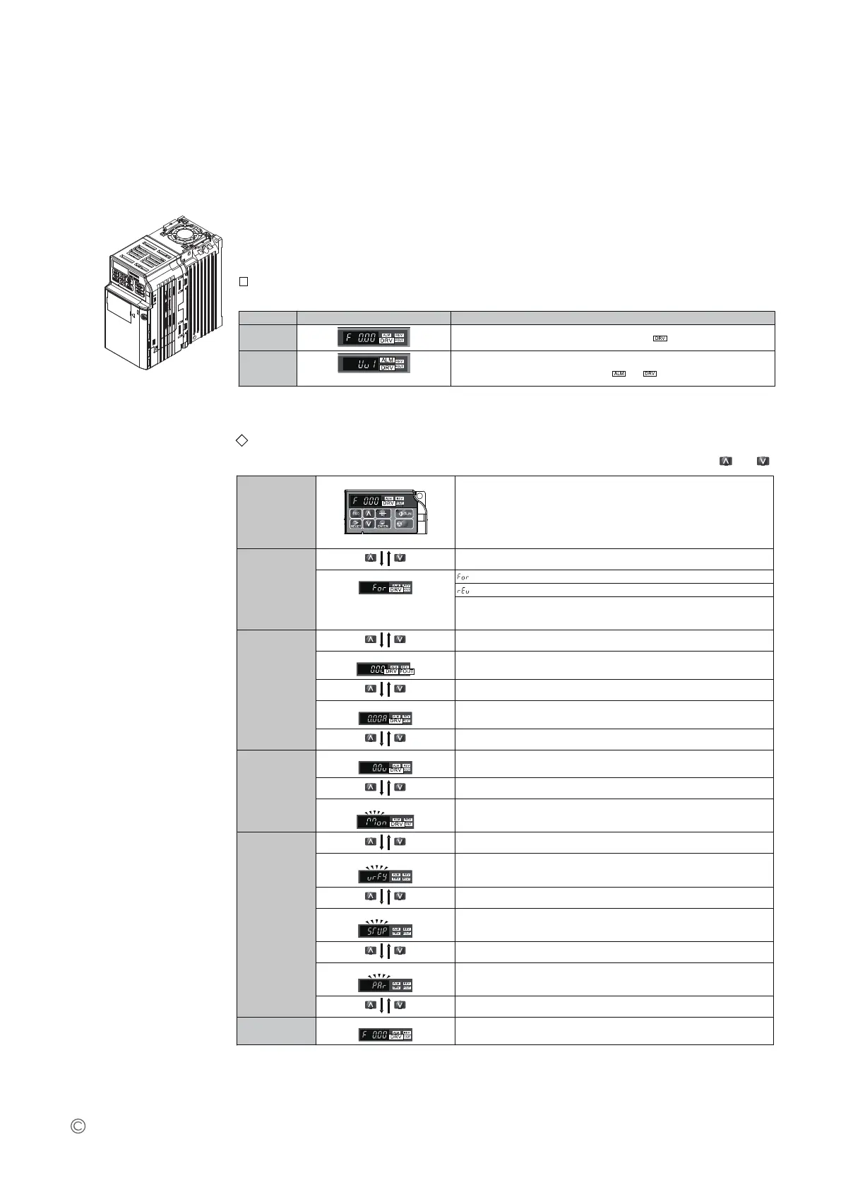
Status Display
When the power supply to the drive is turned on, the LED operator lights will appear as follows:
No. Name Description
Normal
Operation
The data display area displays the frequency reference. is lit.
Fault
Main circuit low voltage (ex)
Data displayed varies by the type of fault.
for more information and possible solution.
and are lit.
Navigating the Drive and Programming Modes
The drive is set to operate in Drive Mode when it is first powered up. Switch between display screens using and .
Power Up
Frequency Reference
STOP
Default Setting
This display screen allows the user to monitor and set the frequency reference while the
drive is running.
Note: The user can select items to display when the drive is first powered up by setting
parameter o1-02.
Drive Mode
Forward/Reverse
: Motor rotates forward.
: Motor rotates in reverse.
Note: For applications that should not run in reverse (fans, pumps, etc.), set parameter
b1-04 = “1” to prohibit the motor from rotating in reverse. This sequence also puts the
drive in LOCAL mode.
Drive Mode
Output Frequency Display
Monitors the frequency output by the drive.
Output Current Display
Monitors the output current of the drive.
Drive Mode
Output Voltage Reference
Monitors the output voltage of the drive.
Monitor Display
Monitor parameters (U parameters) are displayed.
Programming
Mode
Verify Function
Lists all parameters that have been edited or changed from default settings.
Setup
A select list of parameters necessary to get the drive operational quickly.
Parameter Setting
Allows the user to access and edit all parameter settings.
Drive Mode
Frequency Reference
Returns to the frequency reference display screen.
INSTALLATION GUIDE
 Loading...